NOTE: See the NFGC, 13.1.9 and 13.2.20 regarding alternative venting design and the exception, which cover installations such as

the Chimney Adapter Kits KGACA02014FC and KGACA02015FC, which are listed for use with these furnaces.

The Chimney Adapter Kit is listed alternative venting design for these furnaces. See the kit instructions for complete details.

Canada-This furnace is permitted to be vented into a clay tile-lined masonry chimney that is exposed to the outdoors below the roof line, provided:

1.Vent connector is Type-B double-wall, and

2.This furnace is common vented with at least 1 draft hood- equipped appliance, and

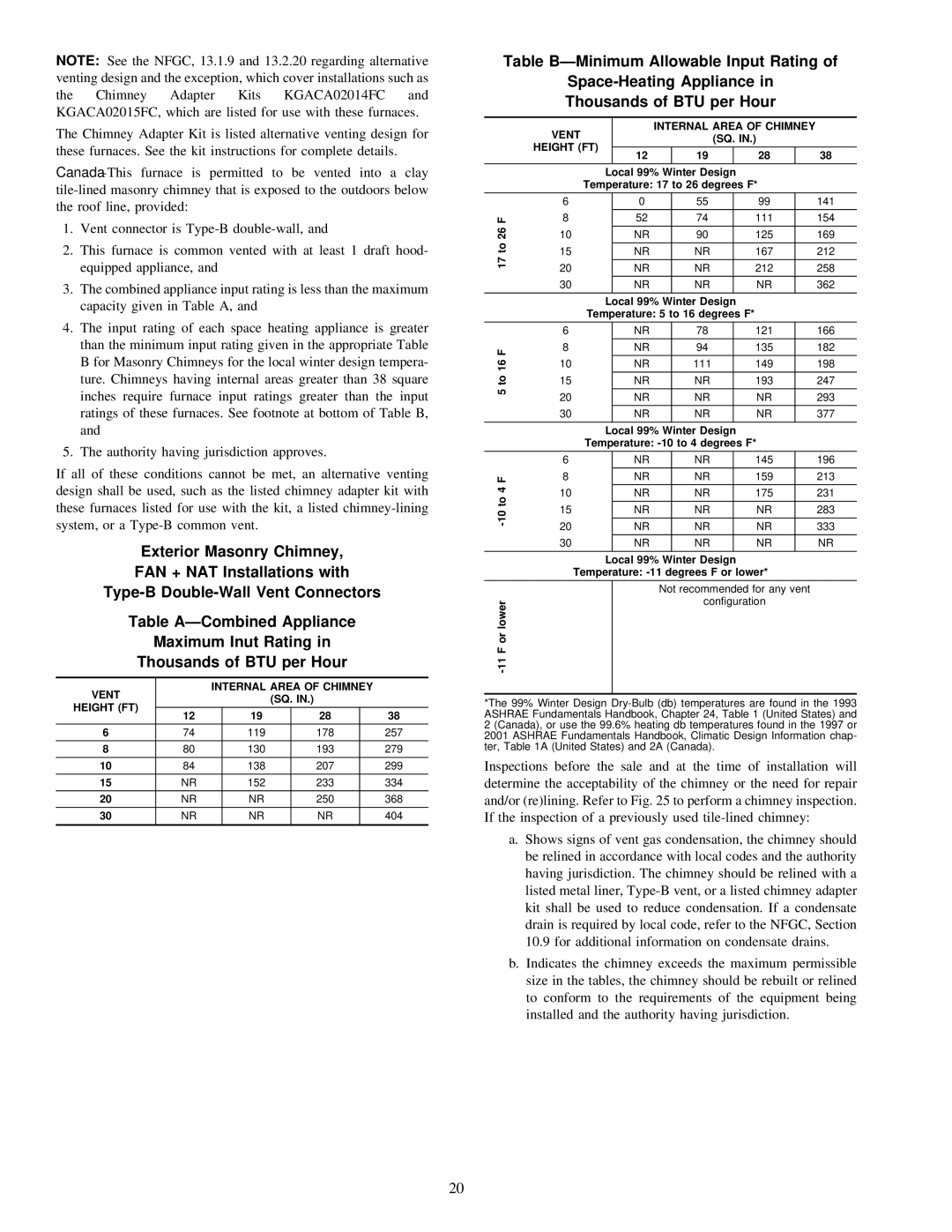
3.The combined appliance input rating is less than the maximum capacity given in Table A, and

4.The input rating of each space heating appliance is greater than the minimum input rating given in the appropriate Table B for Masonry Chimneys for the local winter design tempera- ture. Chimneys having internal areas greater than 38 square inches require furnace input ratings greater than the input ratings of these furnaces. See footnote at bottom of Table B, and

5.The authority having jurisdiction approves.

If all of these conditions cannot be met, an alternative venting design shall be used, such as the listed chimney adapter kit with these furnaces listed for use with the kit, a listed chimney-lining system, or a Type-B common vent.

Exterior Masonry Chimney,

FAN + NAT Installations with

Type-B Double-Wall Vent Connectors

Table A—Combined Appliance

Maximum Inut Rating in

Thousands of BTU per Hour

VENT


INTERNAL AREA OF CHIMNEY


(SQ. IN.)


HEIGHT (FT)


12


19


28


38


6

74


119


178


257


8

80


130


193


279


10

84


138


207


299

15

NR


152


233


334


20

NR


NR


250


368


30

NR


NR


NR


404


Table B—Minimum Allowable Input Rating of

Space-Heating Appliance in Thousands of BTU per Hour


VENT


INTERNAL AREA OF CHIMNEY


(SQ. IN.)


HEIGHT (FT)


12


19


28


38


Local 99% Winter Design


Temperature: 17 to 26 degrees F*


6


0


55


99


141

F

8


52


74


111


154

26


10


NR


90


125


169

to


15


NR


NR


167


212

17


20


NR


NR


212


258


30


NR


NR


NR


362


Local 99% Winter Design


Temperature: 5 to 16 degrees F*


6


NR


78


121


166


F

8


NR


94


135


182

to 16

10


NR


111


149


198


15


NR


NR


193


247

5


20


NR


NR


NR


293


30


NR


NR


NR


377


Local 99% Winter Design


Temperature: -10 to 4 degrees F*


6


NR


NR


145


196


F

8


NR


NR


159


213

4

10


NR


NR


175


231

to


15


NR


NR


NR


283

-10


20


NR


NR


NR


333


30


NR


NR


NR


NR


Local 99% Winter Design


Temperature: -11 degrees F or lower*


Not recommended for any vent


-11 F or lower


configuration


*The 99% Winter Design Dry-Bulb (db) temperatures are found in the 1993 ASHRAE Fundamentals Handbook, Chapter 24, Table 1 (United States) and 2 (Canada), or use the 99.6% heating db temperatures found in the 1997 or 2001 ASHRAE Fundamentals Handbook, Climatic Design Information chap- ter, Table 1A (United States) and 2A (Canada).

Inspections before the sale and at the time of installation will determine the acceptability of the chimney or the need for repair and/or (re)lining. Refer to Fig. 25 to perform a chimney inspection. If the inspection of a previously used tile-lined chimney:

a.Shows signs of vent gas condensation, the chimney should be relined in accordance with local codes and the authority having jurisdiction. The chimney should be relined with a listed metal liner, Type-B vent, or a listed chimney adapter kit shall be used to reduce condensation. If a condensate drain is required by local code, refer to the NFGC, Section

10.9for additional information on condensate drains.

b.Indicates the chimney exceeds the maximum permissible size in the tables, the chimney should be rebuilt or relined to conform to the requirements of the equipment being installed and the authority having jurisdiction.

20

Page 21
Image 21
Bryant 310AAV, 310JAV warranty Vent Internal Area of Chimney

310JAV, 310AAV specifications

The Bryant 310AAV and 310JAV are high-efficiency air conditioning and heating systems designed for residential and light commercial applications. These models embody Bryant's commitment to delivering reliable comfort solutions while prioritizing energy efficiency and performance.

One of the standout features of the Bryant 310AAV and 310JAV is their impressive Seasonal Energy Efficiency Ratio (SEER) ratings. The higher the SEER, the more efficient the unit is in using electricity to cool your space. The Bryant 310AAV boasts a SEER rating of up to 16, while the 310JAV offers a slightly lower rating. This efficiency translates into cost savings on monthly energy bills while ensuring indoor comfort throughout the year.

Both models utilize advanced technologies, including two-stage heating and cooling capabilities. This means that the systems can adjust their operation based on the heating or cooling needs of a space, providing optimal temperature control while reducing energy waste. The two-stage operation also contributes to quieter operation levels, making these units suitable for residential settings where noise is a concern.

The 310AAV and 310JAV are equipped with variable-speed compressors, which further enhance their efficiency and comfort levels. The variable-speed technology allows the system to operate at different speeds, ensuring consistent temperature management and reducing the frequency of on-and-off cycling. This leads to steadier indoor temperatures and improved humidity control.

In addition to their performance features, Bryant places a strong emphasis on durability and dependability. The units are constructed with high-quality materials that are designed to withstand various environmental conditions. Features such as a weather-resistant cabinet and an efficient coil design help protect the units from wear and tear, ensuring long-lasting performance.

The implementation of environmentally friendly refrigerant options is another characteristic that demonstrates Bryant's commitment to sustainability. Both the 310AAV and 310JAV utilize R-410A refrigerant, which has a lower environmental impact compared to older refrigerants, aligning with modern standards for eco-friendly HVAC systems.

Overall, the Bryant 310AAV and 310JAV represent a blend of efficiency, advanced technology, and durability. With their attractive SEER ratings, two-stage operation, variable-speed capabilities, and commitment to sustainability, these models stand out as excellent choices for homeowners and businesses looking to enhance their heating and cooling solutions while keeping energy consumption in check. Whether for residential comfort or light commercial use, these Bryant units promise reliability and performance for years to come.