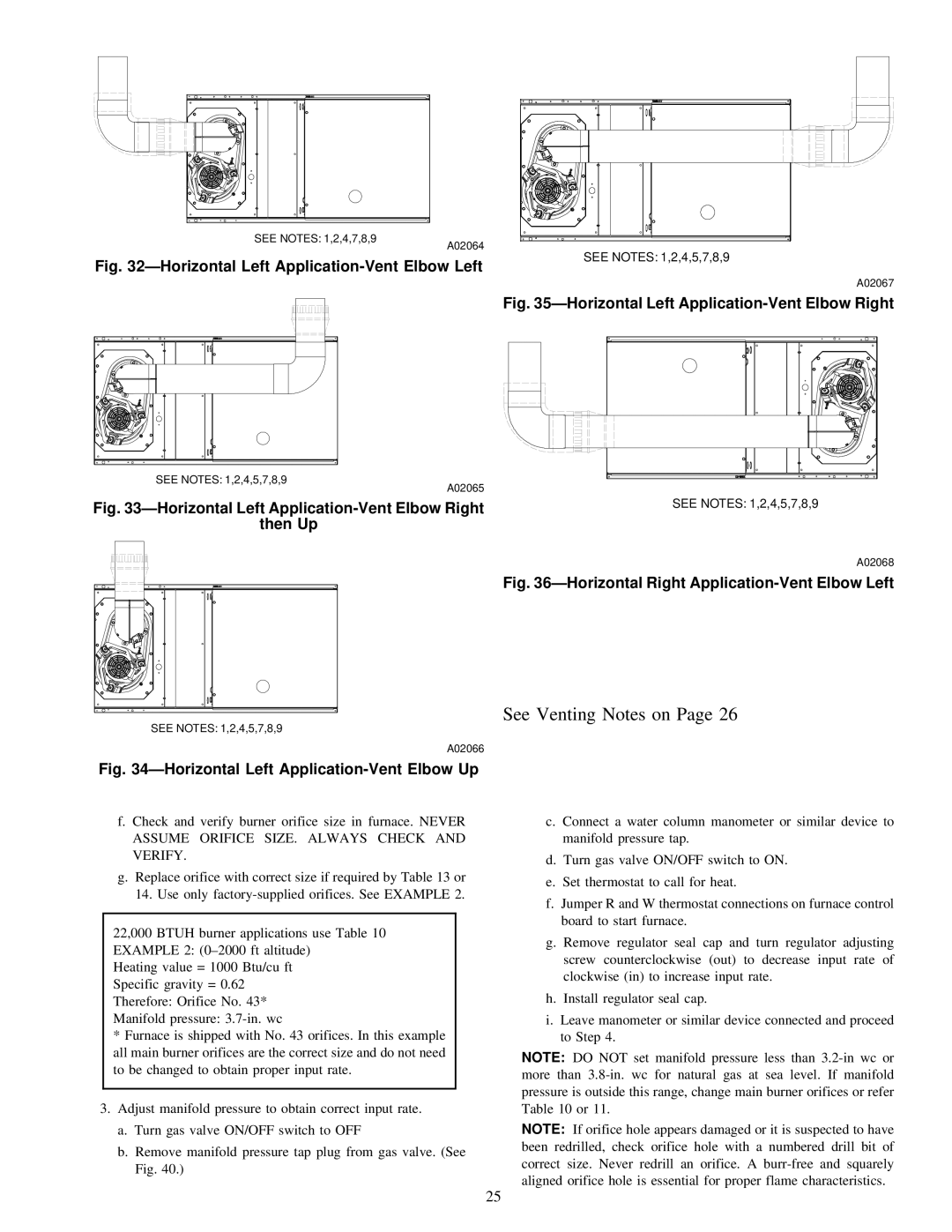
310JAV, 310AAV specifications
The Bryant 310AAV and 310JAV are high-efficiency air conditioning and heating systems designed for residential and light commercial applications. These models embody Bryant's commitment to delivering reliable comfort solutions while prioritizing energy efficiency and performance.One of the standout features of the Bryant 310AAV and 310JAV is their impressive Seasonal Energy Efficiency Ratio (SEER) ratings. The higher the SEER, the more efficient the unit is in using electricity to cool your space. The Bryant 310AAV boasts a SEER rating of up to 16, while the 310JAV offers a slightly lower rating. This efficiency translates into cost savings on monthly energy bills while ensuring indoor comfort throughout the year.
Both models utilize advanced technologies, including two-stage heating and cooling capabilities. This means that the systems can adjust their operation based on the heating or cooling needs of a space, providing optimal temperature control while reducing energy waste. The two-stage operation also contributes to quieter operation levels, making these units suitable for residential settings where noise is a concern.
The 310AAV and 310JAV are equipped with variable-speed compressors, which further enhance their efficiency and comfort levels. The variable-speed technology allows the system to operate at different speeds, ensuring consistent temperature management and reducing the frequency of on-and-off cycling. This leads to steadier indoor temperatures and improved humidity control.
In addition to their performance features, Bryant places a strong emphasis on durability and dependability. The units are constructed with high-quality materials that are designed to withstand various environmental conditions. Features such as a weather-resistant cabinet and an efficient coil design help protect the units from wear and tear, ensuring long-lasting performance.
The implementation of environmentally friendly refrigerant options is another characteristic that demonstrates Bryant's commitment to sustainability. Both the 310AAV and 310JAV utilize R-410A refrigerant, which has a lower environmental impact compared to older refrigerants, aligning with modern standards for eco-friendly HVAC systems.
Overall, the Bryant 310AAV and 310JAV represent a blend of efficiency, advanced technology, and durability. With their attractive SEER ratings, two-stage operation, variable-speed capabilities, and commitment to sustainability, these models stand out as excellent choices for homeowners and businesses looking to enhance their heating and cooling solutions while keeping energy consumption in check. Whether for residential comfort or light commercial use, these Bryant units promise reliability and performance for years to come.