furnace. If the dampers are manually operated, they must be


This gas furnace may be used for construction heat provided


equipped with means to prevent operation of either unit unless the


damper is in the full-heat or full-cool position.


that:


AIR FOR COMBUSTION AND VENTILATION


-The furnace is permanently

installed with

all electrical


Provisions for adequate combustion and ventilation air must be


wiring, piping, venting and ducting installed

according to


provided in accordance with Section 5.3 of the NFGC, Air for


these installation instructions. A return air duct is provided,


Combustion and Ventilation, or applicable provisions of the local


sealed to the furnace casing, and terminated outside the space


building codes.


containing the furnace. This prevents a negative pressure


condition as created by the circulating air blower, causing a


Canadian installations must be installed in accordance with NSC-


flame rollout and/or drawing combustion products into the


NGPIC Part 7 and all authorities having jurisdiction.


structure.


-The furnace is controlled by a thermostat. It may not be hot


wiredto provide heat continuously to the structure without


thermostatic control.


-Clean outside air is provided for combustion. This is to


minimize the corrosive effects of adhesives, sealers and other


construction materials. It also prevents the entrainment of


drywall dust into combustion air, which can cause fouling and


plugging of furnace components.


-The temperature of the return air to the furnace is no less


than 55 degrees F, with no evening setback or shutdown. The


use of the furnace while the structure is under construction is


deemed to be intermittent operation per our installation


instructions.


-The air temperature rise is within the rated rise range on the


furnace rating plate, and the firing rate has been set to the


18-IN. MINIMUM


nameplate value.


TO BURNERS


A93044


-The filters used to clean the circulating air during the


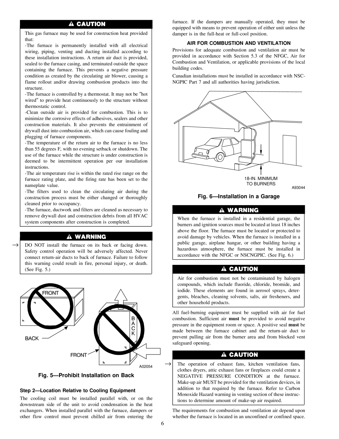
Fig. 6—Installation in a Garage


construction process must be either changed or thoroughly


cleaned prior to occupancy.


-The furnace, ductwork and filters are cleaned as necessary to


remove drywall dust and construction debris from all HVAC


When the furnace is installed in a residential garage, the


system components after construction is completed.


burners and ignition sources must be located at least 18 inches


above the floor. The furnace must be located or protected to


avoid damage by vehicles. When the furnace is installed in a


DO NOT install the furnace

on

its back

or

facing down.


public garage, airplane hangar, or other building having a


Safety control operation will

be

adversely

affected. Never


hazardous atmosphere, the furnace must be installed in


accordance with the NFGC or NSCNGPIC. (See Fig. 6.)


connect return-air ducts to back of furnace. Failure to follow


this warning could result in fire, personal injury, or death.


(See Fig. 5.)


Air for combustion must not be contaminated by halogen


compounds, which include fluoride, chloride, bromide, and


iodide. These elements are found in aerosol sprays, deter-


gents, bleaches, cleaning solvents, salts, air fresheners, and


other household products.


All fuel-burning equipment must be supplied with air for fuel


combustion. Sufficient air must be provided to avoid negative


pressure in the equipment room or space. A positive seal must be


made between the furnace cabinet and the return-air duct to


prevent pulling air from the burner area and from blocked vent


safeguard opening.


A02054


The operation of exhaust fans, kitchen ventilation fans,


clothes dryers, attic exhaust fans or fireplaces could create a


Fig. 5—Prohibit Installation on Back


NEGATIVE PRESSURE CONDITION at the furnace.


Make-up air MUST be provided for the ventilation devices, in


Step 2—Location Relative to Cooling Equipment


addition to that required by the furnace. Refer to Carbon


Monoxide Hazard warning in venting section of these instruc-


The cooling coil must be installed parallel with, or on the


tions to determine amount of make-up air required.


downstream side of the unit to avoid condensation in the heat


The requirements for combustion and ventilation air depend upon


exchangers. When installed parallel with the furnace, dampers or


other flow control must prevent chilled air

from entering the


whether the furnace is located in an unconfined or confined space.

6

Page 7
Image 7
Bryant 310AAV, 310JAV warranty AIR for Combustion and Ventilation, Location Relative to Cooling Equipment

310JAV, 310AAV specifications

The Bryant 310AAV and 310JAV are high-efficiency air conditioning and heating systems designed for residential and light commercial applications. These models embody Bryant's commitment to delivering reliable comfort solutions while prioritizing energy efficiency and performance.

One of the standout features of the Bryant 310AAV and 310JAV is their impressive Seasonal Energy Efficiency Ratio (SEER) ratings. The higher the SEER, the more efficient the unit is in using electricity to cool your space. The Bryant 310AAV boasts a SEER rating of up to 16, while the 310JAV offers a slightly lower rating. This efficiency translates into cost savings on monthly energy bills while ensuring indoor comfort throughout the year.

Both models utilize advanced technologies, including two-stage heating and cooling capabilities. This means that the systems can adjust their operation based on the heating or cooling needs of a space, providing optimal temperature control while reducing energy waste. The two-stage operation also contributes to quieter operation levels, making these units suitable for residential settings where noise is a concern.

The 310AAV and 310JAV are equipped with variable-speed compressors, which further enhance their efficiency and comfort levels. The variable-speed technology allows the system to operate at different speeds, ensuring consistent temperature management and reducing the frequency of on-and-off cycling. This leads to steadier indoor temperatures and improved humidity control.

In addition to their performance features, Bryant places a strong emphasis on durability and dependability. The units are constructed with high-quality materials that are designed to withstand various environmental conditions. Features such as a weather-resistant cabinet and an efficient coil design help protect the units from wear and tear, ensuring long-lasting performance.

The implementation of environmentally friendly refrigerant options is another characteristic that demonstrates Bryant's commitment to sustainability. Both the 310AAV and 310JAV utilize R-410A refrigerant, which has a lower environmental impact compared to older refrigerants, aligning with modern standards for eco-friendly HVAC systems.

Overall, the Bryant 310AAV and 310JAV represent a blend of efficiency, advanced technology, and durability. With their attractive SEER ratings, two-stage operation, variable-speed capabilities, and commitment to sustainability, these models stand out as excellent choices for homeowners and businesses looking to enhance their heating and cooling solutions while keeping energy consumption in check. Whether for residential comfort or light commercial use, these Bryant units promise reliability and performance for years to come.