FACTORY

INSTALLED

LOCATION

POWER ENTRY HOLE


FILLER PLUG (FACTORY-

UNUSED 7/8-IN. (22 mm)

SUPPLIED LOOSE PARTS BAG)

DIAMETER POWER


ENTRY HOLES

A05113

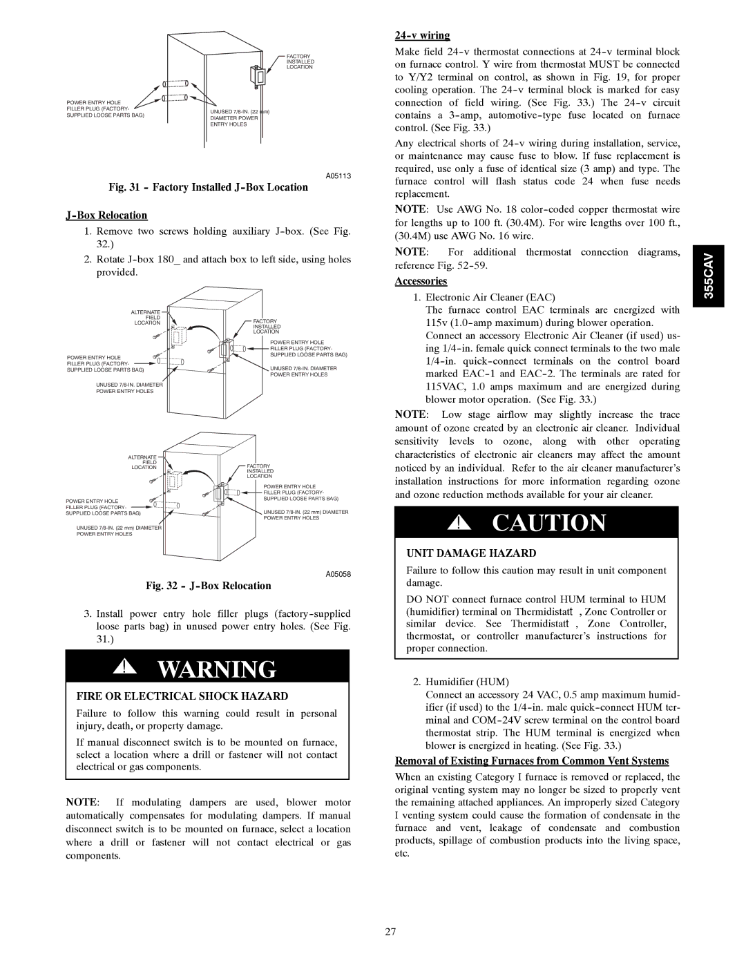
Fig. 31 - Factory Installed J-Box Location

J-Box Relocation

1.Remove two screws holding auxiliary J-box. (See Fig. 32.)

2.Rotate J-box 180_ and attach box to left side, using holes provided.

24-v wiring

Make field 24-v thermostat connections at 24-v terminal block on furnace control. Y wire from thermostat MUST be connected to Y/Y2 terminal on control, as shown in Fig. 19, for proper cooling operation. The 24-v terminal block is marked for easy connection of field wiring. (See Fig. 33.) The 24-v circuit contains a 3-amp, automotive-type fuse located on furnace control. (See Fig. 33.)

Any electrical shorts of 24-v wiring during installation, service, or maintenance may cause fuse to blow. If fuse replacement is required, use only a fuse of identical size (3 amp) and type. The furnace control will flash status code 24 when fuse needs replacement.

NOTE: Use AWG No. 18 color-coded copper thermostat wire for lengths up to 100 ft. (30.4M). For wire lengths over 100 ft., (30.4M) use AWG No. 16 wire.

NOTE: For additional thermostat connection diagrams, reference Fig. 52-59.

Accessories

1. Electronic Air Cleaner (EAC)

The furnace control EAC terminals are energized with

355CAV

ALTERNATE

FIELD

LOCATION

POWER ENTRY HOLE FILLER PLUG (FACTORY- SUPPLIED LOOSE PARTS BAG)

UNUSED 7/8-IN. DIAMETER

POWER ENTRY HOLES

ALTERNATE

FIELD

LOCATION

POWER ENTRY HOLE FILLER PLUG (FACTORY- SUPPLIED LOOSE PARTS BAG)

UNUSED 7/8-IN. (22 mm) DIAMETER

POWER ENTRY HOLES

FACTORY

INSTALLED

LOCATION

POWER ENTRY HOLE FILLER PLUG (FACTORY- SUPPLIED LOOSE PARTS BAG)

UNUSED 7/8-IN. DIAMETER

POWER ENTRY HOLES

FACTORY

INSTALLED

LOCATION

POWER ENTRY HOLE FILLER PLUG (FACTORY- SUPPLIED LOOSE PARTS BAG)

UNUSED 7/8-IN. (22 mm) DIAMETER POWER ENTRY HOLES

115v (1.0-amp maximum) during blower operation.

Connect an accessory Electronic Air Cleaner (if used) us-

ing 1/4-in. female quick connect terminals to the two male

1/4-in. quick-connect terminals on the control board

marked EAC-1 and EAC-2. The terminals are rated for

115VAC, 1.0 amps maximum and are energized during

blower motor operation. (See Fig. 33.)

NOTE: Low stage airflow may slightly increase the trace amount of ozone created by an electronic air cleaner. Individual sensitivity levels to ozone, along with other operating characteristics of electronic air cleaners may affect the amount noticed by an individual. Refer to the air cleaner manufacturer’s installation instructions for more information regarding ozone and ozone reduction methods available for your air cleaner.

!CAUTION

UNIT DAMAGE HAZARD

A05058

Fig. 32 - J-Box Relocation

3.Install power entry hole filler plugs (factory-supplied loose parts bag) in unused power entry holes. (See Fig. 31.)

!WARNING

FIRE OR ELECTRICAL SHOCK HAZARD

Failure to follow this warning could result in personal injury, death, or property damage.

If manual disconnect switch is to be mounted on furnace, select a location where a drill or fastener will not contact electrical or gas components.

NOTE: If modulating dampers are used, blower motor automatically compensates for modulating dampers. If manual disconnect switch is to be mounted on furnace, select a location where a drill or fastener will not contact electrical or gas components.

Failure to follow this caution may result in unit component damage.

DO NOT connect furnace control HUM terminal to HUM (humidifier) terminal on Thermidistatt, Zone Controller or similar device. See Thermidistatt, Zone Controller, thermostat, or controller manufacturer’s instructions for proper connection.

2.Humidifier (HUM)

Connect an accessory 24 VAC, 0.5 amp maximum humid- ifier (if used) to the 1/4-in. male quick-connect HUM ter- minal and COM-24V screw terminal on the control board thermostat strip. The HUM terminal is energized when blower is energized in heating. (See Fig. 33.)

Removal of Existing Furnaces from Common Vent Systems

When an existing Category I furnace is removed or replaced, the original venting system may no longer be sized to properly vent the remaining attached appliances. An improperly sized Category I venting system could cause the formation of condensate in the furnace and vent, leakage of condensate and combustion products, spillage of combustion products into the living space, etc.

27

Page 27
Image 27
Bryant 355CAV Accessories, Fire or Electrical Shock Hazard, Removal of Existing Furnaces from Common Vent Systems

355CAV specifications

The Bryant 355CAV is a state-of-the-art automated vertical machining center designed to enhance precision and efficiency in the manufacturing sector. Renowned for its robust construction, this machine is engineered to handle a broad spectrum of machining tasks, making it suitable for both small and large-scale production environments.

One of the standout features of the Bryant 355CAV is its advanced CNC control system, which provides users with exceptional ease of use. The intuitive user interface allows operators to program complex machining operations with minimal effort, significantly reducing setup times. The machine's high-speed spindle achieves impressive rotational speeds, which allows for quick material removal, ultimately optimizing productivity and throughput.

The Bryant 355CAV exhibits superior rigidity and stability due to its solid cast iron frame and carefully designed structural components. This construction minimizes vibrations during machining, ensuring that even the most intricate parts are produced with high accuracy. The machine's precision ground linear guideways further enhance its performance by providing smooth motion and high load capacity.

Equipped with a large work envelope, the Bryant 355CAV enables manufacturers to accommodate various part sizes and geometries. Additionally, its automatic tool changers can hold a variety of tools, thus facilitating quick transitions between different machining operations without requiring manual intervention. This flexibility is essential for meeting the diverse needs of modern manufacturing.

Another notable characteristic of the Bryant 355CAV is its energy-efficient design. It integrates modern technologies aimed at reducing power consumption while maintaining optimum performance. This environmentally conscious approach not only cuts operational costs but also aligns with the growing demand for sustainable manufacturing practices.

Moreover, the Bryant 355CAV features advanced monitoring capabilities, allowing operators to track machine performance in real time. Data analytics from these systems can be utilized to improve operational efficiency, reduce downtime, and enhance predictive maintenance protocols.

In summary, the Bryant 355CAV is a versatile, high-performance machining center that showcases cutting-edge features and technologies. Its combination of user-friendly controls, sturdy construction, energy efficiency, and advanced monitoring positions it as a vital asset for manufacturers aiming to elevate their productivity and precision in an increasingly competitive landscape.