355CAV

NOTE: Reference Fig. 52-59:

1.Heat pump MUST have a high pressure switch for dual fuel applications.

2.Refer to outdoor equipment Installation Instructions for additional information and setup procedure.

3.Select the “ZONE” position on the two-speed heat pump control.

4.Outdoor Air Temperature Sensor must be attached in all dual fuel applications.

5.Dip switch No.1 on Thermidistat should be set in OFF po- sition for air conditioner installations. This is factory de- fault.

6.Dip switch No. 1 on Thermidistat should be set in ON po- sition for heat pump installations.

7.Dip switch No. 2 on Thermidistat should be set in OFF position for single-speed compressor operation. This is factory default.

8.Dip switch No. 2 on Thermidistat should be set in ON po- sition for two-speed compressor operation.

9.Configuration Option No. 10 “Dual Fuel Selection” must be turned ON in all dual fuel applications.

10.NO connection should be made to the furnace HUM ter- minal when using a Thermidistat.

11.Optional connection. If wire is connected to W2 on fur- nace control board, either dip switch SW1-2 or SW4-2 on furnace control should be set in ON position to allow Thermidistat/Thermostat to control furnace at 2 stages Low/High or Medium/High.

12.Optional connection. If wire is connected, ACRDJ jumper on furnace control should be removed to allow Thermidis- tat/Thermostat to control outdoor unit staging.

13.Furnace must control its own staging operation via furnace control algorithm. This is factory default.

14.The RVS Sensing terminal “L” should not be connected. This is internally used to sense defrost operation.

15.DO NOT SELECT the “FURNACE INTERFACE” or “BALANCE POINT” option on the two-speed heat pump control board. This is controlled internally by the Thermi- distat/Dual Fuel Thermostat.

16.Dip switch D on Dual Fuel Thermostat should be set in OFF position for single-speed compressor operation. This is factory default.

17.Dip switch D on Dual Fuel Thermostat should be set in ON position for two-speed compressor operation.

Step 4 — Adjustments

Set Gas Input Rate

Furnace gas input rate on rating plate is for installations at altitudes up to 2000 ft. (609.6M).

In the USA., the input rating for altitudes above 2000 ft. (609.6M) must be reduced by 2 percent for each 1000 ft.

(304.8M) above sea level.

In Canada, the input rating must be derated by 5 percent for altitudes of 2000 ft. (609.6M) to 4500 ft. (1371.6M) above sea level.

Adjust manifold pressure to obtain input rate.

Furnace input rate must be within +2 percent of input rate on furnace rating plate.

1.Determine natural gas orifice size and manifold pressure for correct input.

a.Obtain average heat value (at installed altitude) from local gas supplier.

b.Obtain average specific gravity from local gas supplier.

c.Verify furnace model. Table 10 can only be used for mod- el 355CAV Furnaces.

d.Find installation altitude in Table 10.

NOTE: For Canadian altitudes of 2000 to 4500 ft. (609.6 to 1371.6M), use USA. altitudes of 2001 to 3000 ft. (609.6 to 914.4M) in Table 10.

e.Find closest natural gas heat value and specific gravity in Table 10.

f.Follow heat value and specific gravity lines to point of intersection to find orifice size and low-, medium-, and high-heat manifold pressure settings for proper opera- tion.

EXAMPLE: 0 - 2000 ft. (0 - 609.6M) altitude Heating value = 1050 Btu/cu ft.

Specific gravity = 0.62 Therefore: Orifice No. 45

Manifold pressure: 3.8-in. wc for high heat 1.6-in. wc for medium heat 0.6-in. wc for low heat

*Furnace is shipped with No. 45 orifices. In this example, all main burner orifices are the correct size and do not need to be changed to obtain proper input rate.

g.Check and verify burner orifice size in furnace. NEVER ASSUME ORIFICE SIZE; ALWAYS CHECK AND VERIFY.

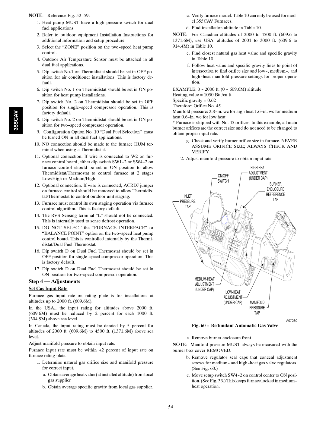
2.Adjust manifold pressure to obtain input rate.


HIGH-HEAT


ON/OFF

ADJUSTMENT


(UNDER CAP)


SWITCH


BURNER


ENCLOSURE

INLET


REFFERENCE


TAP

PRESSURE


TAP


MEDIUM-HEAT ADJUSTMENT

(UNDER CAP)

LOW-HEAT

ADJUSTMENT

(UNDER CAP) MANIFOLD PRESSURE

TAP

A07280

Fig. 60 - Redundant Automatic Gas Valve

a. Remove burner enclosure front.

NOTE: Manifold pressure MUST always be measured with the burner box cover REMOVED.

b. Remove regulator seal caps that conceal adjustment screws for medium- and high-heat gas valve regulators. (See Fig. 60.)

c.Move setup switch SW4-2 on control center to ON posi- tion. (See Fig. 33.) This keeps furnace locked in medium- heat operation.

54

Page 54
Image 54
Bryant 355CAV installation instructions Set Gas Input Rate, Redundant Automatic Gas Valve

355CAV specifications

The Bryant 355CAV is a state-of-the-art automated vertical machining center designed to enhance precision and efficiency in the manufacturing sector. Renowned for its robust construction, this machine is engineered to handle a broad spectrum of machining tasks, making it suitable for both small and large-scale production environments.

One of the standout features of the Bryant 355CAV is its advanced CNC control system, which provides users with exceptional ease of use. The intuitive user interface allows operators to program complex machining operations with minimal effort, significantly reducing setup times. The machine's high-speed spindle achieves impressive rotational speeds, which allows for quick material removal, ultimately optimizing productivity and throughput.

The Bryant 355CAV exhibits superior rigidity and stability due to its solid cast iron frame and carefully designed structural components. This construction minimizes vibrations during machining, ensuring that even the most intricate parts are produced with high accuracy. The machine's precision ground linear guideways further enhance its performance by providing smooth motion and high load capacity.

Equipped with a large work envelope, the Bryant 355CAV enables manufacturers to accommodate various part sizes and geometries. Additionally, its automatic tool changers can hold a variety of tools, thus facilitating quick transitions between different machining operations without requiring manual intervention. This flexibility is essential for meeting the diverse needs of modern manufacturing.

Another notable characteristic of the Bryant 355CAV is its energy-efficient design. It integrates modern technologies aimed at reducing power consumption while maintaining optimum performance. This environmentally conscious approach not only cuts operational costs but also aligns with the growing demand for sustainable manufacturing practices.

Moreover, the Bryant 355CAV features advanced monitoring capabilities, allowing operators to track machine performance in real time. Data analytics from these systems can be utilized to improve operational efficiency, reduce downtime, and enhance predictive maintenance protocols.

In summary, the Bryant 355CAV is a versatile, high-performance machining center that showcases cutting-edge features and technologies. Its combination of user-friendly controls, sturdy construction, energy efficiency, and advanced monitoring positions it as a vital asset for manufacturers aiming to elevate their productivity and precision in an increasingly competitive landscape.