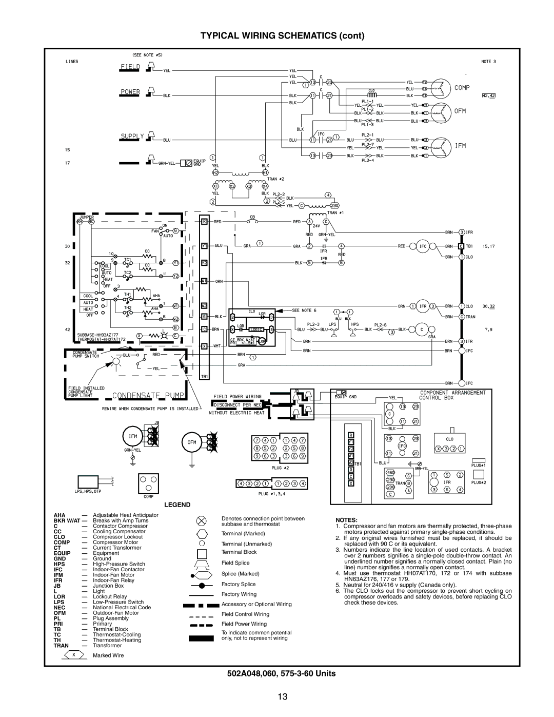
TYPICAL WIRING SCHEMATICS (cont)
LEGEND
AHA | — | Adjustable Heat Anticipator |
|
|
|
|
| Denotes connection point between |
BKR W/AT — | Breaks with Amp Turns |
|
|
|
|
| ||
|
|
|
|
| subbase and thermostat | |||
C | — | Contactor Compressor |
|
|
|
|
| |
|
|
|
|
|
| |||
CC | — | Cooling Compensator |
|
|
|
|
| Terminal (Marked) |
CLO | — | Compressor Lockout |
|
|
|
|
| |
|
|
|
|
|
| |||
COMP | — | Compressor Motor |
|
|
|
|
| Terminal (Unmarked) |
CT | — | Current Transformer |
|
|
|
|
| |
|
|
|
|
| Terminal Block | |||
EQUIP | — | Equipment |
|
|
|
|
| |
GND | — | Ground |
|
|
|
|
| Field Splice |
HPS | — |
|
|
|
|
| ||
IFC | — |
|
|
|
|
| Splice (Marked) | |
IFM | — |
|
|
|
|
| ||
IFR | — |
|
|
|
|
| Factory Splice | |
JB | — | Junction Box |
|
|
|
|
| |
L | — | Light |
|
|
|
|
| Factory Wiring |
LOR | — | Lockout Relay |
|
|
|
|
| |
|
|
|
|
|
| |||
LPS | — |
|
|
|
|
| Accessory or Optional Wiring | |
NEC | — | National Electrical Code |
|
|
|
|
| |
|
|
|
|
|
| |||
OFM | — |
|
|
|
|
| Field Control Wiring | |
PL | — | Plug Assembly |
|
|
|
|
|
|
PRI | — | Primary |
|
|
|
|
| Field Power Wiring |
TB | — | Terminal Block |
|
|
|
|
| To indicate common potential |
TC | — |
|
|
|
|
| ||
|
|
|
|
| only, not to represent wiring | |||
TH | — |
|
|
|
|
| ||
|
|
|
|
|
| |||
TRAN | — | Transformer |
|
|
|
|
|
|
Marked Wire
NOTES:
1.Compressor and fan motors are thermally protected,
2.If any original wires furnished must be replaced, it should be replaced with 90 C or its equivalent.
3.Numbers indicate the line location of used contacts. A bracket over 2 numbers signifies a
4.Must use thermostat HH07AT170, 172 or 174 with subbase HN63AZ176, 177 or 179.
5.Neutral for 240/416 v supply (Canada only).
6.The CLO locks out the compressor to prevent short cycling on compressor overloads and safety devices, before replacing CLO check these devices.
502A048,060, 575-3-60 Units
13