TYPICAL WIRING SCHEMATICS (cont)
|
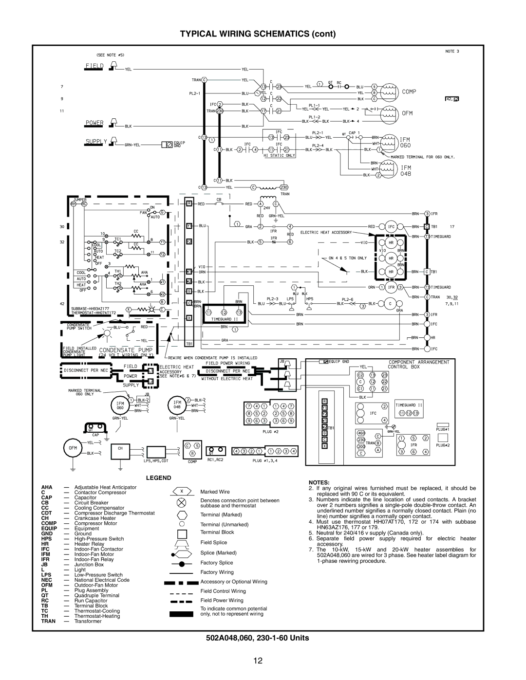
| LEGEND |
|
|
|
|
| |
AHA | — Adjustable Heat Anticipator |
|
|
|
| Marked Wire | ||
C | — Contactor Compressor |
|
|
|
| |||
CAP | — | Capacitor |
|
|
|
| Denotes connection point between | |
CB | — | Circuit Breaker |
|
|
|
| ||
|
|
|
| subbase and thermostat | ||||
CC | — Cooling Compensator |
|
|
|
| |||
|
|
|
|
| ||||
CDT | — | Compressor Discharge Thermostat |
|
|
|
| Terminal (Marked) | |
CH | — Crankcase Heater |
|
|
|
| |||
|
|
|
|
| ||||
COMP | — Compressor Motor |
|
|
|
| Terminal (Unmarked) | ||
EQUIP | — Equipment |
|
|
|
| Terminal Block | ||
GND | — Ground |
|
|
|
| |||
HPS | — |
|
|
|
| Field Splice | ||
HR | — Heater Relay |
|
|
|
| |||
IFC | — |
|
|
|
| Splice (Marked) | ||
IFM | — |
|
|
|
| |||
IFR | — |
|
|
|
| Factory Splice | ||
JB | — Junction Box |
|
|
|
| |||
|
|
|
|
| ||||
L | — | Light |
|
|
|
| Factory Wiring | |
LPS | — |
|
|
|
| |||
|
|
|
|
| ||||
NEC | — | National Electrical Code |
|
|
|
|
| Accessory or Optional Wiring |
OFM | — |
|
|
|
|
| ||
|
|
|
|
|
| |||
PL | — Plug Assembly |
|
|
|
| Field Control Wiring | ||
QT | — Quadruple Terminal |
|
|
|
| Field Power Wiring | ||
RC | — Run Capacitor |
|
|
|
| |||
TB | — | Terminal Block |
|
|
|
| To indicate common potential | |
TC | — |
|
|
|
| |||
|
|
|
| only, not to represent wiring | ||||
TH | — |
|
|
|
| |||
|
|
|
|
| ||||
TRAN | — Transformer |
|
|
|
|
| ||
NOTES:
2.If any original wires furnished must be replaced, it should be replaced with 90 C or its equivalent.
3.Numbers indicate the line location of used contacts. A bracket over 2 numbers signifies a
4.Must use thermostat HH07AT170, 172 or 174 with subbase HN63AZ176, 177 or 179.
5.Neutral for 240/416 v supply (Canada only).
6.Separate field power supply required for electric heater accessory.
7.The
502A048,060, 230-1-60 Units
12