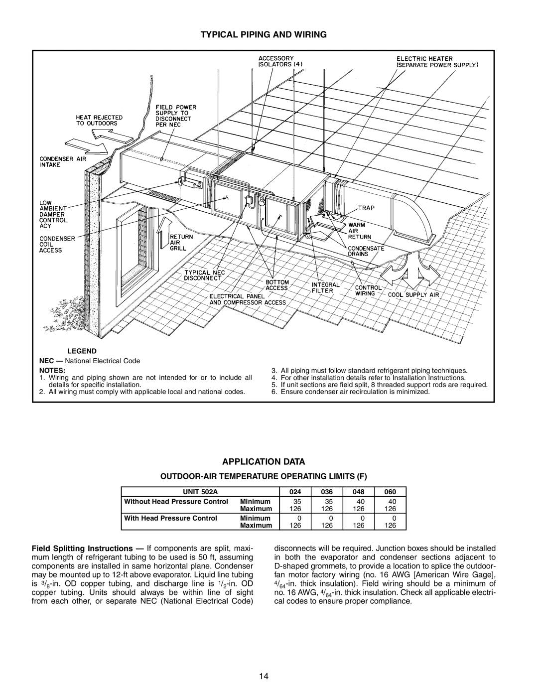
TYPICAL PIPING AND WIRING
LEGEND
NEC — National Electrical Code
NOTES:
1.Wiring and piping shown are not intended for or to include all details for specific installation.
2.All wiring must comply with applicable local and national codes.
3.All piping must follow standard refrigerant piping techniques.
4.For other installation details refer to Installation Instructions.
5.If unit sections are field split, 8 threaded support rods are required.
6.Ensure condenser air recirculation is minimized.
APPLICATION DATA
OUTDOOR-AIR TEMPERATURE OPERATING LIMITS (F)
UNIT 502A |
| 024 | 036 | 048 | 060 |
Without Head Pressure Control | Minimum | 35 | 35 | 40 | 40 |
| Maximum | 126 | 126 | 126 | 126 |
With Head Pressure Control | Minimum | 0 | 0 | 0 | 0 |
| Maximum | 126 | 126 | 126 | 126 |
Field Splitting Instructions — If components are split, maxi- mum length of refrigerant tubing to be used is 50 ft, assuming components are installed in same horizontal plane. Condenser may be mounted up to
disconnects will be required. Junction boxes should be installed in both the evaporator and condenser sections adjacent to
14