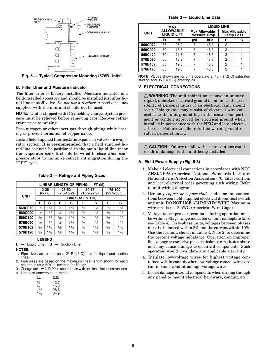
Fig. 5 Ð Typical Compressor Mounting (576B Units)
B. Filter Drier and Moisture Indicator
The ®lter drier is factory installed. Moisture indicator is a
NOTE: Unit is shipped with
Pass nitrogen or other inert gas through piping while braz- ing to prevent formation of copper oxide.
Install
| Table 2 Ð Refrigerant Piping Sizes |
|
| |||||||||
|
|
|
|
|
|
|
|
|
| |||
| LINEAR LENGTH OF PIPING Ð FT (M) |
|
| |||||||||
|
|
|
|
| ||||||||
UNIT |
|
| ||||||||||
|
|
|
| Line Size (in. OD) |
|
| ||||||
|
|
|
|
|
|
| ||||||
| L | S | L |
| S |
| L |
| S |
| L | S |
569C072 | 1¤2 | 11¤8 | 1¤2 |
| 11¤8 |
| 1¤2 |
| 11¤8 |
| 1¤2 | 11¤8 |
569C090 | 1¤2 | 11¤8 | 1¤2 |
| 11¤8 |
| 5¤8 |
| 11¤8 |
| 5¤8 | 13¤8 |
569C120 | 5¤8 | 11¤8 | 5¤8 |
| 13¤8 |
| 5¤8 |
| 13¤8 |
| 5¤8 | 13¤8 |
576B090 | 1¤2 | 11¤8 | 1¤2 |
| 11¤8 |
| 5¤8 |
| 11¤8 |
| 5¤8 | 13¤8 |
576B102 | 5¤8 | 11¤8 | 5¤8 |
| 11¤8 |
| 5¤8 |
| 13¤8 |
| 5¤8 | 13¤8 |
576B120 | 5¤8 | 11¤8 | 5¤8 |
| 11¤8 |
| 5¤8 |
| 13¤8 |
| 5¤8 | 13¤8 |
| LEGEND |
|
|
|
|
|
|
|
|
|
| |
L Ð Liquid Line | S Ð Suction Line |
|
|
|
|
|
| |||||
NOTES:
1.Pipe sizes are based on a 2° F (1° C) loss for liquid and suction lines.
2.Pipe sizes are based on the maximum linear length shown for each column, plus a 50% allowance for ®ttings.
3.Charge units with
4.Line size conversion to mm is:
in. mm
1¤2 | 12.7 |
5¤8 | 15.9 |
11¤8 | 28.6 |
13¤8 | 34.9 |
Table 3 Ð Liquid Line Data
|
| MAX |
| LIQUID LINE |
| |||
UNIT | ALLOWABLE | Max Allowable | Max Allowable | |||||
LIQUID LIFT | Pressure Drop | Temp Loss | ||||||
| ||||||||
| Ft |
| M | psi | kPa | F | C | |
569C072 | 86 |
| 26.2 | 7 | 48.3 | 2 | 1 | |
569C090 | 60 |
| 18.3 | 7 | 48.3 | 2 | 1 | |
569C120 | 70 |
| 21.3 | 7 | 48.3 | 2 | 1 | |
576B090 | 60 |
| 18.3 | 7 | 48.3 | 2 | 1 | |
576B102 | 65 |
| 19.8 | 7 | 48.3 | 2 | 1 | |
576B120 | 65 |
| 19.8 | 7 | 48.3 | 2 | 1 | |
|
|
|
|
|
|
|
| |
NOTE: Values shown are for units operating at 45 F (7.2 C) saturated suction and 95 F (35 C) entering air.
V.ELECTRICAL CONNECTIONS
![]() WARNING: The unit cabinet must have an uninter- rupted, unbroken electrical ground to minimize the pos- sibility of personal injury if an electrical fault should occur. This ground may consist of electrical wire con- nected to the unit ground lug in the control compart- ment or conduit approved for electrical ground when installed in accordance with the NEC and local electri- cal codes. Failure to adhere to this warning could re- sult in personal injury.
WARNING: The unit cabinet must have an uninter- rupted, unbroken electrical ground to minimize the pos- sibility of personal injury if an electrical fault should occur. This ground may consist of electrical wire con- nected to the unit ground lug in the control compart- ment or conduit approved for electrical ground when installed in accordance with the NEC and local electri- cal codes. Failure to adhere to this warning could re- sult in personal injury.
![]() CAUTION: Failure to follow these precautions could result in damage to the unit being installed:
CAUTION: Failure to follow these precautions could result in damage to the unit being installed:
A.Field Power Supply (Fig. 6-8)
1.Make all electrical connections in accordance with NEC ANSI/NFPA (American National Standards Institute/ National Fire Protection Association) 70, latest edition, and local electrical codes governing such wiring. Refer to unit wiring diagram.
2.Use only copper or
3.Voltage to compressor terminals during operation must be within voltage range indicated on unit nameplate (also see Table 4). On
4.Insulate
5.Do not damage internal components when drilling through any panel to mount electrical hardware, conduit, etc.