All units except
Refer to unit label diagram for additional information. Pig- tails are provided for ®eld wire connections. Use factory- supplied splices or UL (Underwriters' Laboratories) approved copper/aluminum connector.
When installing units, provide a disconnect per NEC.
All ®eld wiring must comply with NEC and local requirements.
Install ®eld wiring as follows:
1.Install conduit through side panel openings.
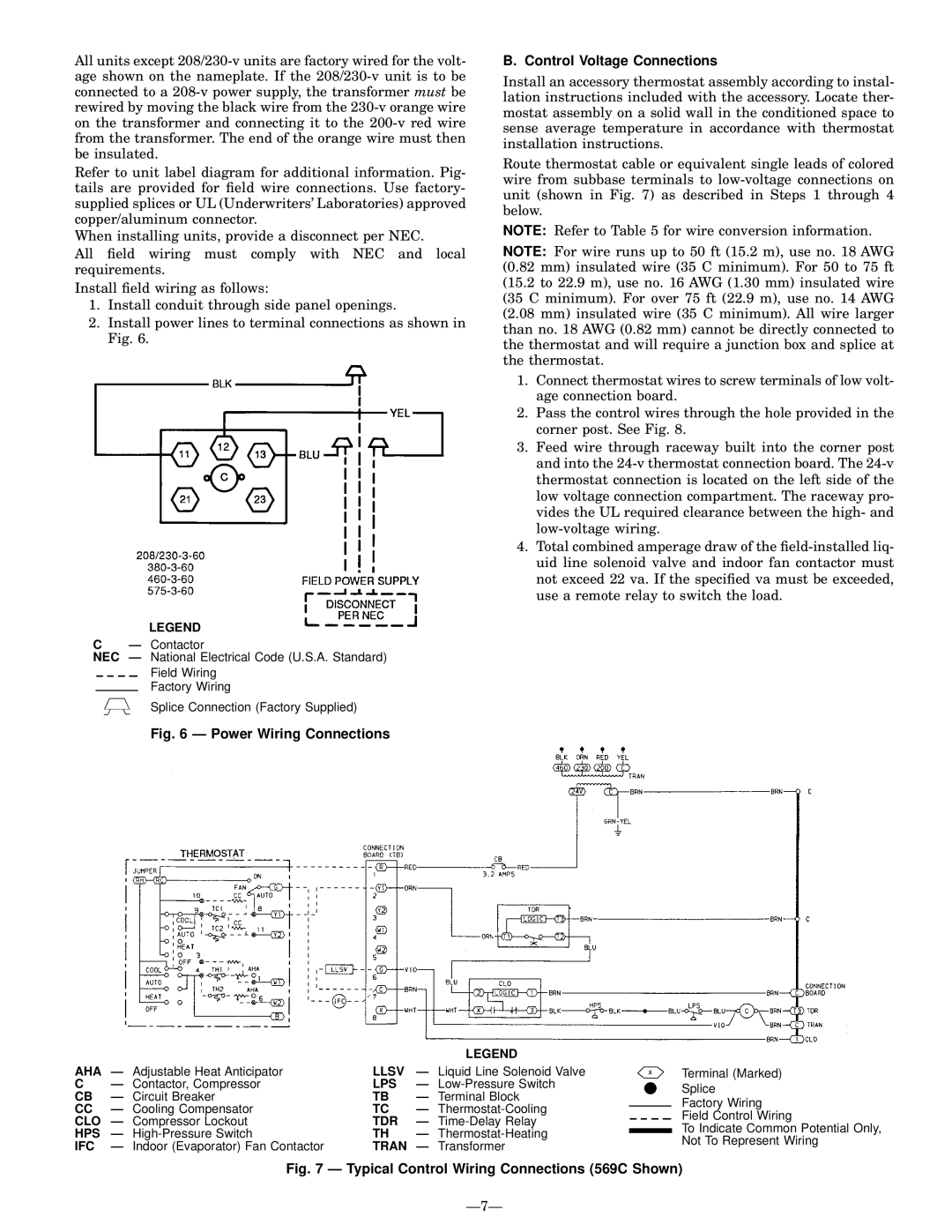
2.Install power lines to terminal connections as shown in Fig. 6.
LEGEND
CÐ Contactor
NEC Ð National Electrical Code (U.S.A. Standard)
Field Wiring
Factory Wiring
Splice Connection (Factory Supplied)
Fig. 6 Ð Power Wiring Connections
B. Control Voltage Connections
Install an accessory thermostat assembly according to instal- lation instructions included with the accessory. Locate ther- mostat assembly on a solid wall in the conditioned space to sense average temperature in accordance with thermostat installation instructions.
Route thermostat cable or equivalent single leads of colored wire from subbase terminals to
NOTE: Refer to Table 5 for wire conversion information.
NOTE: For wire runs up to 50 ft (15.2 m), use no. 18 AWG (0.82 mm) insulated wire (35 C minimum). For 50 to 75 ft (15.2 to 22.9 m), use no. 16 AWG (1.30 mm) insulated wire (35 C minimum). For over 75 ft (22.9 m), use no. 14 AWG (2.08 mm) insulated wire (35 C minimum). All wire larger than no. 18 AWG (0.82 mm) cannot be directly connected to the thermostat and will require a junction box and splice at the thermostat.
1.Connect thermostat wires to screw terminals of low volt- age connection board.
2.Pass the control wires through the hole provided in the corner post. See Fig. 8.
3.Feed wire through raceway built into the corner post and into the
4.Total combined amperage draw of the
|
|
| LEGEND |
| |
AHA | Ð Adjustable Heat Anticipator | LLSV | Ð Liquid Line Solenoid Valve | Terminal (Marked) | |
C | Ð Contactor, Compressor | LPS | Ð | Splice | |
CB | Ð Circuit Breaker | TB | Ð Terminal Block | ||
Factory Wiring | |||||
CC | Ð Cooling Compensator | TC | Ð | ||
Field Control Wiring | |||||
CLO Ð Compressor Lockout | TDR | Ð | |||
To Indicate Common Potential Only, | |||||
HPS | Ð | TH | Ð | ||
Not To Represent Wiring | |||||
IFC | Ð Indoor (Evaporator) Fan Contactor | TRAN Ð Transformer | |||
| |||||