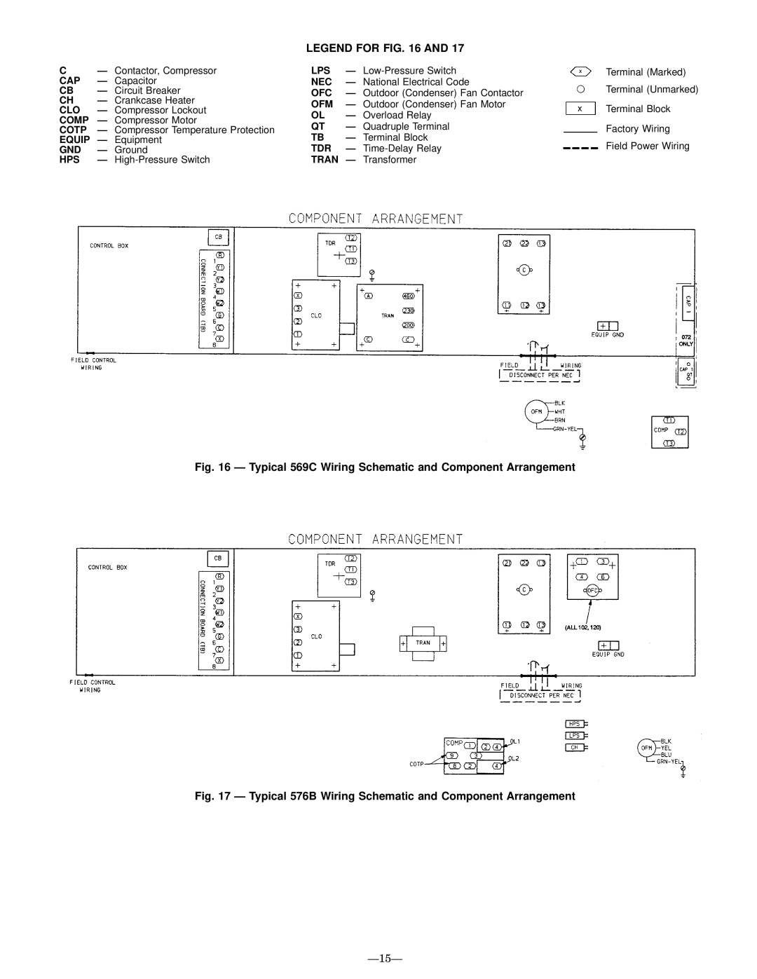
LEGEND FOR FIG. 16 AND 17
C | Ð Contactor, Compressor | LPS | Ð | Terminal (Marked) | |
CAP | Ð Capacitor | NEC | Ð National Electrical Code | Terminal (Unmarked) | |
CB | Ð Circuit Breaker | OFC | Ð Outdoor (Condenser) Fan Contactor | ||
CH | Ð Crankcase Heater | OFM | Ð Outdoor (Condenser) Fan Motor | Terminal Block | |
CLO | Ð Compressor Lockout | ||||
OL | Ð Overload Relay | ||||
COMP | Ð Compressor Motor |
| |||
QT | Ð Quadruple Terminal | Factory Wiring | |||
COTP | Ð Compressor Temperature Protection | ||||
EQUIP | Ð Equipment | TB | Ð Terminal Block | Field Power Wiring | |
GND | Ð Ground | TDR | Ð | ||
HPS | Ð | TRAN Ð Transformer |
| ||