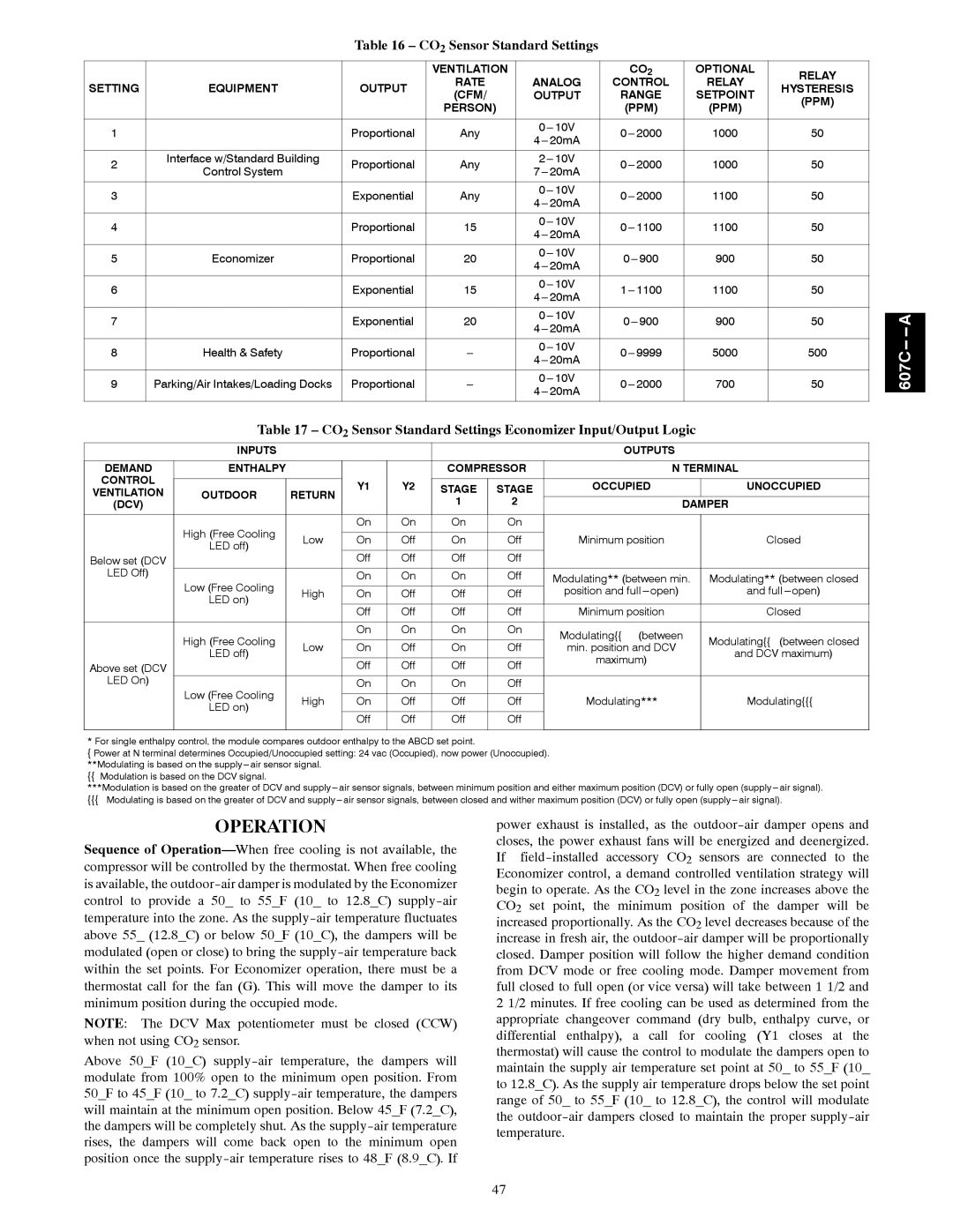
Table 16 – CO2 Sensor Standard Settings
|
|
| VENTILATION |
| CO2 | OPTIONAL | RELAY | |
SETTING | EQUIPMENT | OUTPUT | RATE | ANALOG | CONTROL | RELAY | HYSTERESIS | |
(CFM/ | OUTPUT | RANGE | SETPOINT | |||||
|
|
| (PPM) | |||||
|
|
| PERSON) |
| (PPM) | (PPM) | ||
|
|
|
|
| ||||
|
|
|
|
|
|
|
| |
1 |
| Proportional | Any | 1000 | 50 | |||
| ||||||||
|
|
|
|
|
|
| ||
|
|
|
|
|
|
|
| |
2 | Interface w/Standard Building | Proportional | Any | 1000 | 50 | |||
Control System | ||||||||
|
|
|
|
|
| |||
|
|
|
|
|
|
|
| |
3 |
| Exponential | Any | 1100 | 50 | |||
| ||||||||
|
|
|
|
|
|
| ||
|
|
|
|
|
|
|
| |
4 |
| Proportional | 15 | 1100 | 50 | |||
| ||||||||
|
|
|
|
|
|
| ||
|
|
|
|
|
|
|
| |
5 | Economizer | Proportional | 20 | 900 | 50 | |||
|
|
|
|
|
|
| ||
|
|
|
|
|
|
|
| |
6 |
| Exponential | 15 | 1100 | 50 | |||
| ||||||||
|
|
|
|
|
|
| ||
|
|
|
|
|
|
|
| |
7 |
| Exponential | 20 | 900 | 50 | |||
| ||||||||
|
|
|
|
|
|
| ||
|
|
|
|
|
|
|
| |
8 | Health & Safety | Proportional | 5000 | 500 | ||||
|
|
|
|
|
|
| ||
|
|
|
|
|
|
|
| |
9 | Parking/Air Intakes/Loading Docks | Proportional | 700 | 50 | ||||
|
|
|
|
|
|
| ||
|
|
|
|
|
|
|
|
Table 17 – CO2 Sensor Standard Settings Economizer Input/Output Logic
| INPUTS |
|
|
|
|
| OUTPUTS |
| |
|
|
|
|
|
|
|
|
| |
DEMAND | ENTHALPY |
|
|
| COMPRESSOR | N TERMINAL | |||
CONTROL |
|
|
|
|
|
|
|
| |
|
| Y1 | Y2 | STAGE | STAGE | OCCUPIED | UNOCCUPIED | ||
VENTILATION | OUTDOOR | RETURN | |||||||
|
|
|
| ||||||
(DCV) |
|
|
|
| 1 | 2 | DAMPER | ||
|
|
|
|
|
|
|
|
| |
| High (Free Cooling |
| On | On | On | On |
|
| |
|
|
|
|
|
|
|
| ||
| Low | On | Off | On | Off | Minimum position | Closed | ||
| LED off) | ||||||||
|
|
|
|
|
|
|
| ||
Below set (DCV |
|
| Off | Off | Off | Off |
|
| |
LED Off) |
|
|
|
|
|
|
|
| |
Low (Free Cooling |
| On | On | On | Off | Modulating** (between min. | Modulating** (between closed | ||
| High | On | Off | Off | Off | position and full | and full | ||
| LED on) |
|
|
|
|
|
|
| |
|
|
| Off | Off | Off | Off | Minimum position | Closed | |
|
|
|
|
|
|
|
|
| |
| High (Free Cooling |
| On | On | On | On | Modulating{{ (between | Modulating{{ (between closed | |
|
|
|
|
|
| ||||
| Low | On | Off | On | Off | min. position and DCV | |||
| LED off) | and DCV maximum) | |||||||
|
|
|
|
|
| maximum) | |||
Above set (DCV |
|
| Off | Off | Off | Off |
| ||
|
|
|
| ||||||
LED On) |
|
|
|
|
|
|
|
| |
Low (Free Cooling |
| On | On | On | Off |
|
| ||
|
|
|
|
|
|
|
| ||
| High | On | Off | Off | Off | Modulating*** | Modulating{{{ | ||
| LED on) | ||||||||
|
|
|
|
|
|
|
| ||
|
|
| Off | Off | Off | Off |
|
| |
|
|
|
|
|
|
|
|
| |
* For single enthalpy control, the module compares outdoor enthalpy to the ABCD set point.
{Power at N terminal determines Occupied/Unoccupied setting: 24 vac (Occupied), now power (Unoccupied). **Modulating is based on the
{{Modulation is based on the DCV signal.
***Modulation is based on the greater of DCV and
{{{Modulating is based on the greater of DCV and
607C-- -- A
OPERATION
Sequence of
NOTE: The DCV Max potentiometer must be closed (CCW) when not using CO2 sensor.
Above 50_F (10_C)
power exhaust is installed, as the
47