607C-- -- A
O | T2 C C O | DFT |
|
|
|
|
| OF2 | OF1 |
R | T1 |
|
|
|
|
|
|
|
|
W |
|
|
|
|
|
|
|
|
|
2 |
|
|
|
|
|
|
|
|
|
Y |
|
|
|
|
|
|
|
|
|
C | Y |
|
|
|
|
|
|
|
|
SPEEDUP | P1 |
|
|
|
|
|
|
|
|
J1 | P3 | INTERVALTIMER | 90 | 60 30 | 30 60 | 120 |
|
| |
| DFT |
| OFF |
| QUIET SHIFT | ON |
|
| |
| Speedup |
|
|
|
| Quiet | Defrost interval |
| |
| Pins |
|
|
|
| Shift | DIP switches |
| |
|
|
|
|
|
|
|
|
| A08020 |
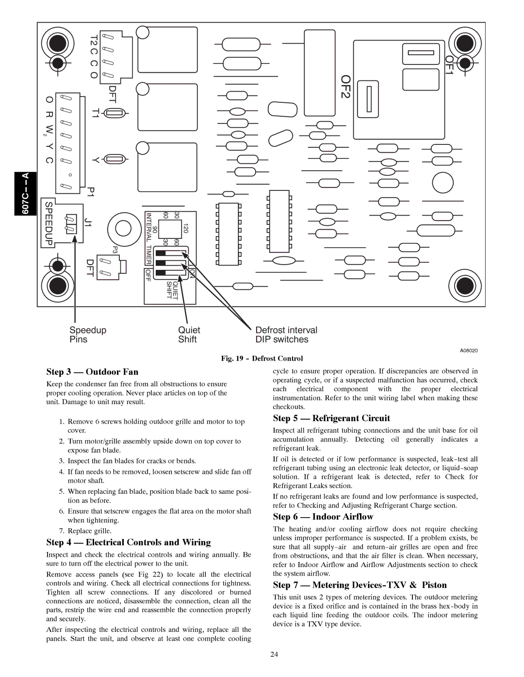
Fig. 19 - Defrost Control
Step 3 — Outdoor Fan | cycle to ensure proper operation. If discrepancies are observed in | |
Keep the condenser fan free from all obstructions to ensure | operating cycle, or if a suspected malfunction has occurred, check | |
each electrical component with the proper electrical | ||
proper cooling operation. Never place articles on top of the | ||
instrumentation. Refer to the unit wiring label when making these | ||
unit. Damage to unit may result. | ||
checkouts. | ||
|
1.Remove 6 screws holding outdoor grille and motor to top cover.
2.Turn motor/grille assembly upside down on top cover to expose fan blade.
3.Inspect the fan blades for cracks or bends.
4.If fan needs to be removed, loosen setscrew and slide fan off motor shaft.
5.When replacing fan blade, position blade back to same posi- tion as before.
6.Ensure that setscrew engages the flat area on the motor shaft when tightening.
7.Replace grille.
Step 4 — Electrical Controls and Wiring
Inspect and check the electrical controls and wiring annually. Be sure to turn off the electrical power to the unit.
Remove access panels (see Fig 22) to locate all the electrical controls and wiring. Check all electrical connections for tightness. Tighten all screw connections. If any discolored or burned connections are noticed, disassemble the connection, clean all the parts, restrip the wire end and reassemble the connection properly and securely.
After inspecting the electrical controls and wiring, replace all the panels. Start the unit, and observe at least one complete cooling
Step 5 — Refrigerant Circuit
Inspect all refrigerant tubing connections and the unit base for oil accumulation annually. Detecting oil generally indicates a refrigerant leak.
If oil is detected or if low performance is suspected,
If no refrigerant leaks are found and low performance is suspected, refer to Checking and Adjusting Refrigerant Charge section.
Step 6 — Indoor Airflow
The heating and/or cooling airflow does not require checking unless improper performance is suspected. If a problem exists, be sure that all
Step 7 — Metering Devices-TXV & Piston
This unit uses 2 types of metering devices. The outdoor metering device is a fixed orifice and is contained in the brass
24
