Section 2 — Installation
Bryant
2.6TOTAL CIRCUIT ISOLATION
METHOD
When a generator capable of powering all electrical loads in the circuit is to be installed, the “Total Circuit Isolation Method” may be used. The following apply to the transfer switch in this type of system.
•Ampere rating of the transfer switch must equal the ampere rating of the normal incoming utility service.
•The transfer switch is installed between the utility service entrance and the building distribution panel.
2.7GROUNDING THE GENERATOR
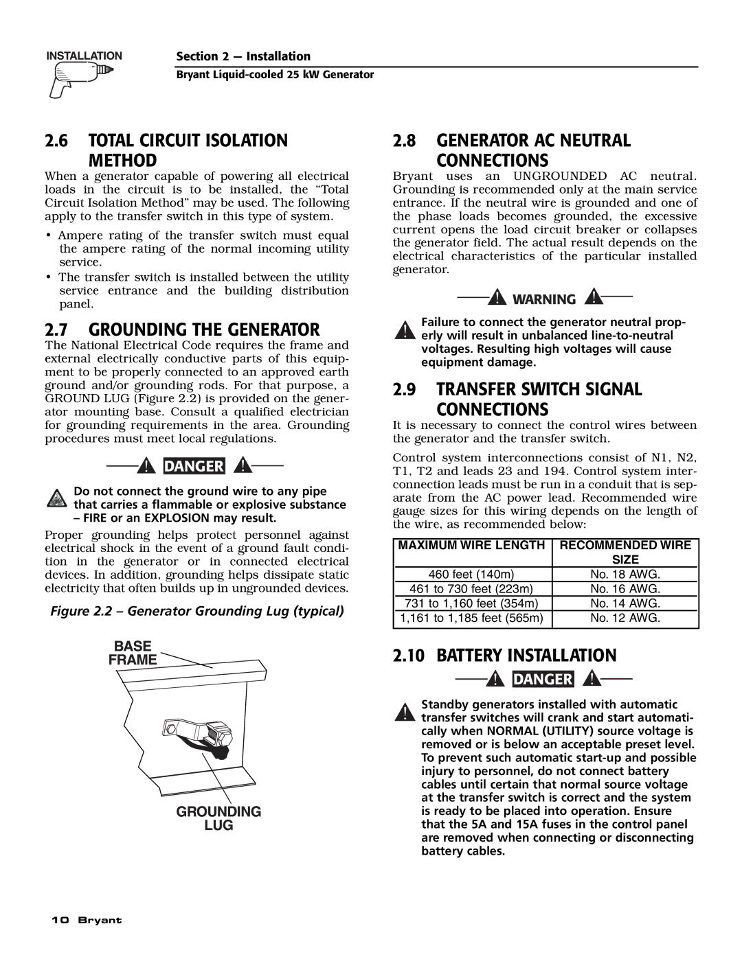
The National Electrical Code requires the frame and external electrically conductive parts of this equip- ment to be properly connected to an approved earth ground and/or grounding rods. For that purpose, a GROUND LUG (Figure 2.2) is provided on the gener- ator mounting base. Consult a qualified electrician for grounding requirements in the area. Grounding procedures must meet local regulations.
![]()
![]() DANGER
DANGER
Do not connect the ground wire to any pipe that carries a flammable or explosive substance
– FIRE or an EXPLOSION may result.
Proper grounding helps protect personnel against electrical shock in the event of a ground fault condi- tion in the generator or in connected electrical devices. In addition, grounding helps dissipate static electricity that often builds up in ungrounded devices.
Figure 2.2 – Generator Grounding Lug (typical)
2.8GENERATOR AC NEUTRAL
CONNECTIONS
Bryant uses an UNGROUNDED AC neutral. Grounding is recommended only at the main service entrance. If the neutral wire is grounded and one of the phase loads becomes grounded, the excessive current opens the load circuit breaker or collapses the generator field. The actual result depends on the electrical characteristics of the particular installed generator.
Failure to connect the generator neutral prop-
!erly will result in unbalanced
2.9TRANSFER SWITCH SIGNAL
CONNECTIONS
It is necessary to connect the control wires between the generator and the transfer switch.
Control system interconnections consist of N1, N2, T1, T2 and leads 23 and 194. Control system inter- connection leads must be run in a conduit that is sep- arate from the AC power lead. Recommended wire gauge sizes for this wiring depends on the length of the wire, as recommended below:
| MAXIMUM WIRE LENGTH | RECOMMENDED WIRE |
|
|
| SIZE |
|
| 460 feet (140m) | No. 18 AWG. |
|
| 461 to 730 feet (223m) | No. 16 AWG. |
|
| 731 to 1,160 feet (354m) | No. 14 AWG. |
|
| 1,161 to 1,185 feet (565m) | No. 12 AWG. |
|
|
|
|
|
2.10BATTERY INSTALLATION
![]()
![]() DANGER
DANGER ![]()
Standby generators installed with automatic
!transfer switches will crank and start automati- cally when NORMAL (UTILITY) source voltage is removed or is below an acceptable preset level. To prevent such automatic
10 Bryant