Section 2 — Installation
Bryant
•AGRICULTURAL WIRING HANDBOOK, obtainable from the Food and Energy Council, 909 University Avenue, Columbia, MO, 65201.
•ASAE EP-364.2, INSTALLATION AND MAINTE-
NANCE OF FARM STANDBY ELECTRIC POWER, available from the American Society of Agricultural Engineers, 2950 Niles Road, St. Joseph, MI 49085.
•A52.1, AMERICAN NATIONAL STANDARD FOR CHIMNEYS, FIREPLACES AND VENTING SYS- TEMS, available from the American National Standard Institute, 1430 Broadway, New York, N.Y. 10018.
2.2GENERATOR LOCATION
Install the generator set, in its protective enclosure outdoors, where adequate cooling and ventilating air always is available. Consider these factors:
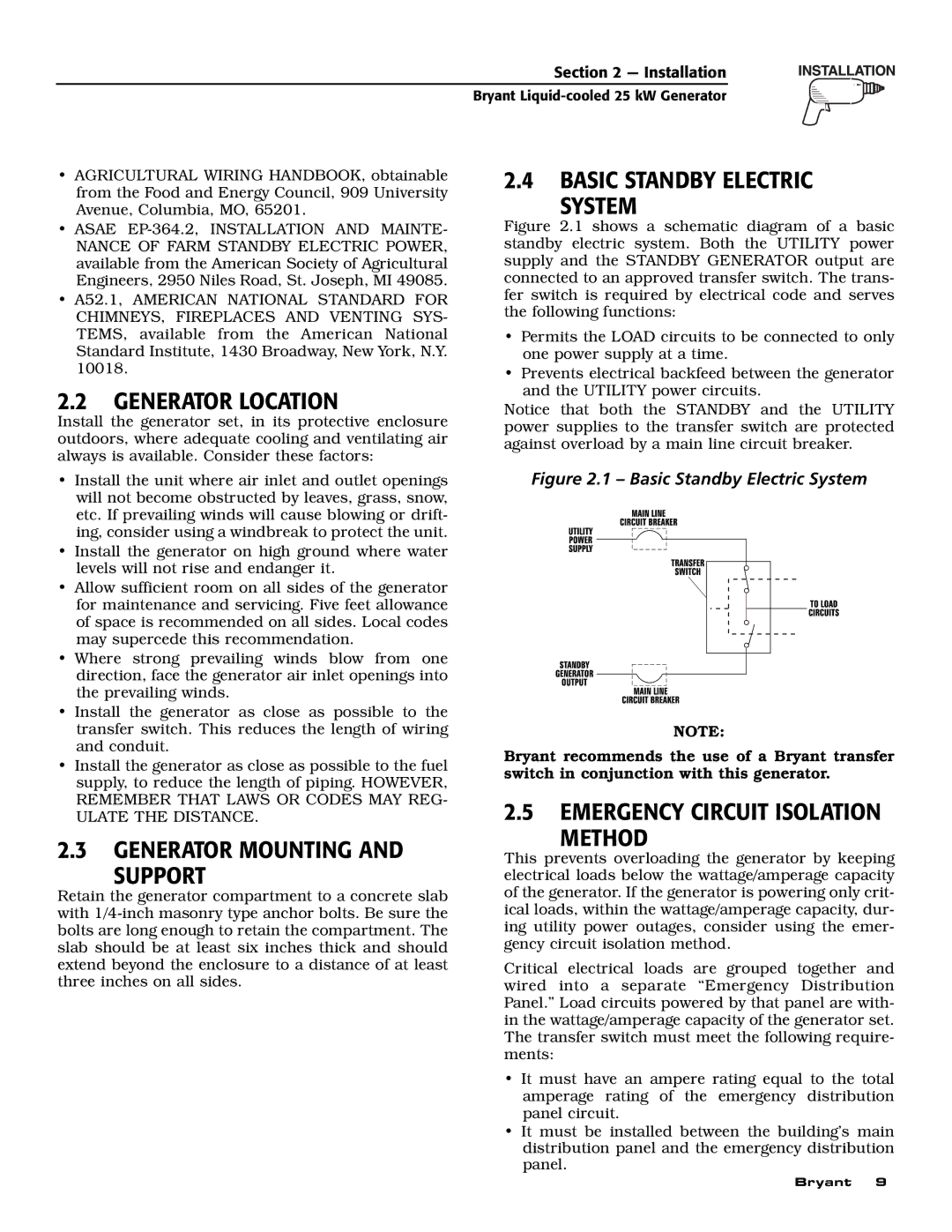
2.4BASIC STANDBY ELECTRIC
SYSTEM
Figure 2.1 shows a schematic diagram of a basic standby electric system. Both the UTILITY power supply and the STANDBY GENERATOR output are connected to an approved transfer switch. The trans- fer switch is required by electrical code and serves the following functions:
•Permits the LOAD circuits to be connected to only one power supply at a time.
•Prevents electrical backfeed between the generator and the UTILITY power circuits.
Notice that both the STANDBY and the UTILITY power supplies to the transfer switch are protected against overload by a main line circuit breaker.
•Install the unit where air inlet and outlet openings will not become obstructed by leaves, grass, snow, etc. If prevailing winds will cause blowing or drift- ing, consider using a windbreak to protect the unit.
•Install the generator on high ground where water levels will not rise and endanger it.
•Allow sufficient room on all sides of the generator for maintenance and servicing. Five feet allowance of space is recommended on all sides. Local codes may supercede this recommendation.
•Where strong prevailing winds blow from one direction, face the generator air inlet openings into the prevailing winds.
•Install the generator as close as possible to the transfer switch. This reduces the length of wiring and conduit.
•Install the generator as close as possible to the fuel supply, to reduce the length of piping. HOWEVER, REMEMBER THAT LAWS OR CODES MAY REG- ULATE THE DISTANCE.
2.3GENERATOR MOUNTING AND
SUPPORT
Retain the generator compartment to a concrete slab with
Figure 2.1 – Basic Standby Electric System
NOTE:
Bryant recommends the use of a Bryant transfer switch in conjunction with this generator.
2.5EMERGENCY CIRCUIT ISOLATION
METHOD
This prevents overloading the generator by keeping electrical loads below the wattage/amperage capacity of the generator. If the generator is powering only crit- ical loads, within the wattage/amperage capacity, dur- ing utility power outages, consider using the emer- gency circuit isolation method.
Critical electrical loads are grouped together and wired into a separate “Emergency Distribution Panel.” Load circuits powered by that panel are with- in the wattage/amperage capacity of the generator set. The transfer switch must meet the following require- ments:
•It must have an ampere rating equal to the total amperage rating of the emergency distribution panel circuit.
•It must be installed between the building’s main distribution panel and the emergency distribution panel.
Bryant 9