Section 3 - Operation
Bryant
2.11.2 TRANSFER SWITCH
If this generator is used to supply power to any elec- trical system normally powered by an electric utility, the National Electrical Code requires that a transfer switch be installed. The transfer switch prevents elec- trical backfeed between two different electrical sys- tems, (for additional information, see the applicable transfer switch manual for this unit). The transfer switch, as well as the generator and other standby components, must be properly located and mounted in strict compliance with applicable codes, standards and regulations.
2.11.3 FUEL SYSTEM
Make sure the fuel supply system to the generator (a) delivers the correct fuel at the correct pressure and volume and, (b) is properly purged and leak tested according to code. No fuel leakage is permitted.
3.1CONTROL CONSOLE
COMPONENTS
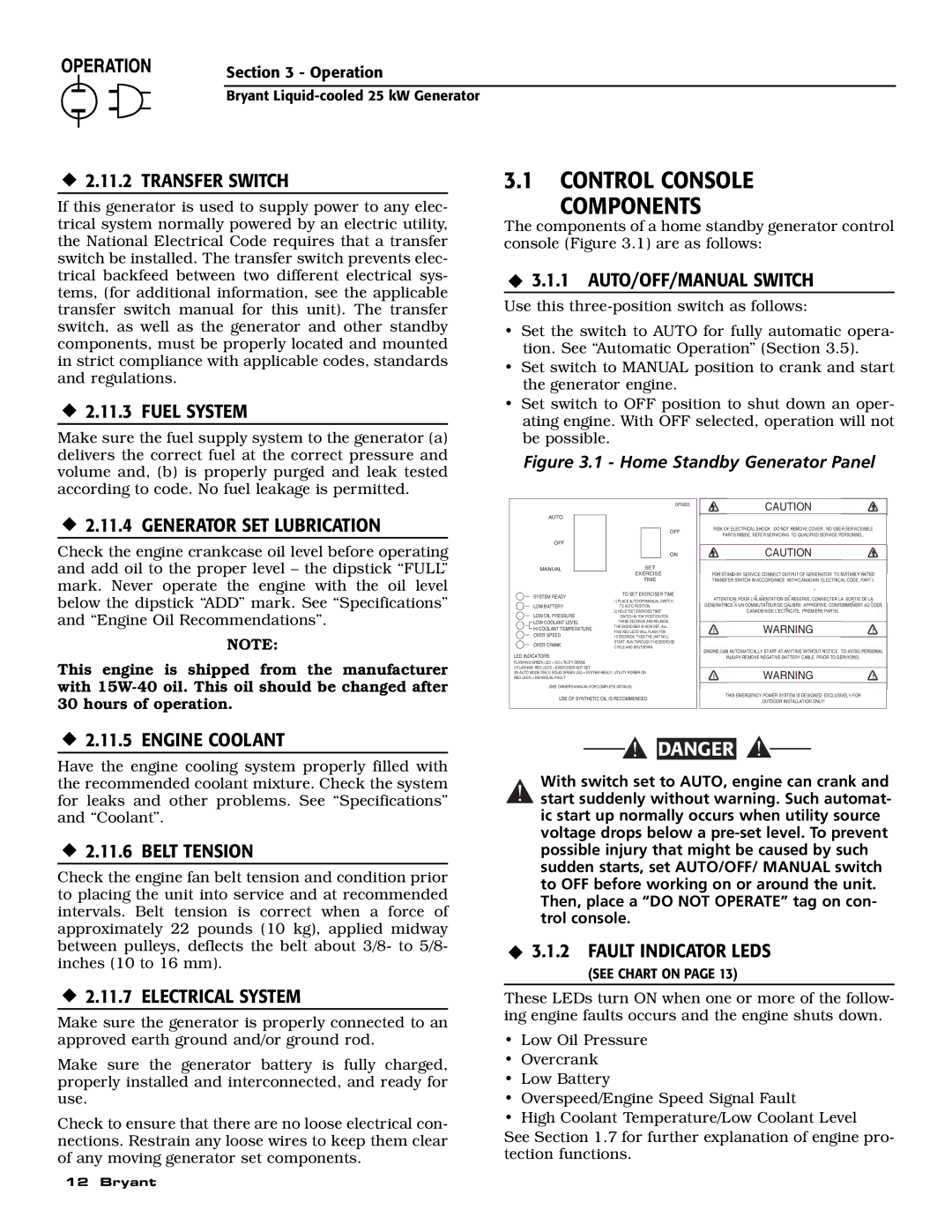
The components of a home standby generator control console (Figure 3.1) are as follows:
3.1.1 AUTO/OFF/MANUAL SWITCH
Use this
•Set the switch to AUTO for fully automatic opera- tion. See “Automatic Operation” (Section 3.5).
•Set switch to MANUAL position to crank and start the generator engine.
•Set switch to OFF position to shut down an oper- ating engine. With OFF selected, operation will not be possible.
Figure 3.1 - Home Standby Generator Panel
2.11.4 GENERATOR SET LUBRICATION
Check the engine crankcase oil level before operating and add oil to the proper level – the dipstick “FULL” mark. Never operate the engine with the oil level below the dipstick “ADD” mark. See “Specifications” and “Engine Oil Recommendations”.
NOTE:
AUTO
OFF
MANUAL
SYSTEM READY
LOW BATTERY
LOW OIL PRESSURE
![]() LOW COOLANT LEVEL
LOW COOLANT LEVEL
![]() HI COOLANT TEMPERATURE
HI COOLANT TEMPERATURE ![]() OVER SPEED
OVER SPEED
OVER CRANK
LED INDICATORS:
0F0653
OFF
ON
SET
EXERCISE
TIME
TO SET EXERCISER TIME
1)PLACE AUTO/OFF/MANUAL SWITCH TO AUTO POSITION.
2)HOLD "SET EXERCISE TIME" SWITCH IN "ON" POSITION FOR
THREE SECONDS AND RELEASE. THE EXERCISER IS NOW SET. ALL FIVE RED LED'S WILL FLASH FOR
10 SECONDS. THEN THE UNIT WILL START, RUN THROUGH THE EXERCISE CYCLE AND SHUTDOWN.
CAUTION
RISK OF ELECTRICAL SHOCK. DO NOT REMOVE COVER. NO USER SERVICEABLE
PARTS INSIDE. REFER SERVICING TO QUALIFIED SERVICE PERSONNEL.
CAUTION
FOR
ATTENTION: POUR L'ALIMENTATION DE RESERVE, CONNECTER LA SORTIE DE LA ICE A UN COMMUTATEUR DE CALIBRE APPROPRIE, CONFO
CANADIEN DE L'ECTRICITE, PREMIERE PARTIE.
WARNING
N AUTOMATICALLY START AT ANYTIME WITHOUT NOTICE. T
INJURY REMOVE NEGATIVE BATTERY CABLE PRIOR TO SE
This engine is shipped from the manufacturer with
FLASHING GREEN LED = NO UTILITY SENSE
5 FLASHING RED LED'S = EXERCISER NOT SET
(IN AUTO MODE ONLY) SOLID GREEN LED = SYSTEM READY, UTILITY POWER ON RED LED'S = INDIVIDUAL FAULT
(SEE OWNER'S MANUAL FOR COMPLETE DETAILS)
USE OF SYNTHETIC OIL IS RECOMMENDED
WARNING
THIS EMERGENCY POWER SYSTEM IS DESIGNED EXCLUSIVELY FOR
OUTDOOR INSTALLATION ONLY!
2.11.5 ENGINE COOLANT
Have the engine cooling system properly filled with the recommended coolant mixture. Check the system for leaks and other problems. See “Specifications” and “Coolant”.
2.11.6 BELT TENSION
Check the engine fan belt tension and condition prior to placing the unit into service and at recommended intervals. Belt tension is correct when a force of approximately 22 pounds (10 kg), applied midway between pulleys, deflects the belt about 3/8- to 5/8- inches (10 to 16 mm).
2.11.7 ELECTRICAL SYSTEM
Make sure the generator is properly connected to an approved earth ground and/or ground rod.
Make sure the generator battery is fully charged, properly installed and interconnected, and ready for use.
Check to ensure that there are no loose electrical con- nections. Restrain any loose wires to keep them clear of any moving generator set components.
12 Bryant
![]()
![]() DANGER
DANGER
With switch set to AUTO, engine can crank and
!start suddenly without warning. Such automat- ic start up normally occurs when utility source voltage drops below a
3.1.2 FAULT INDICATOR LEDS
(SEE CHART ON PAGE 13)
These LEDs turn ON when one or more of the follow- ing engine faults occurs and the engine shuts down.
•Low Oil Pressure
•Overcrank
•Low Battery
•Overspeed/Engine Speed Signal Fault
•High Coolant Temperature/Low Coolant Level
See Section 1.7 for further explanation of engine pro- tection functions.