Bulldog Security RS1100E manual 
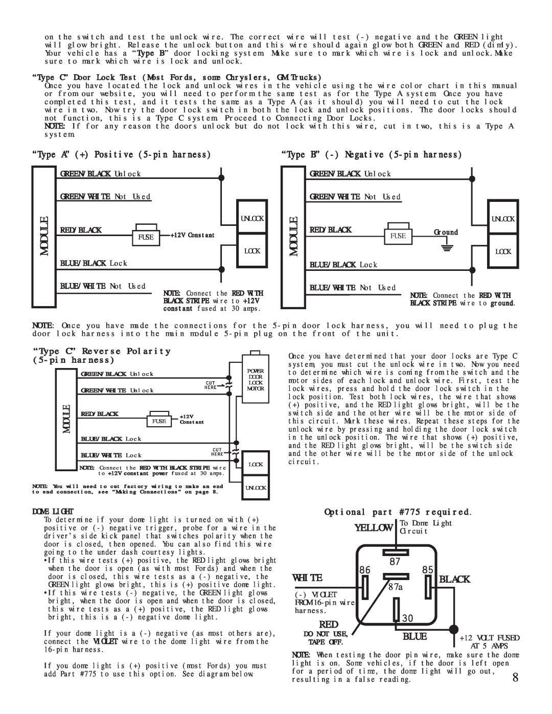
Module, White, “Type A” + Positive 5-pin harness, Red/Black

Models: RS1100E RS114

1 11
Download 11 pages 32.42 Kb
Page 9
Image 9
“Type C” Door Lock Test (Most Fords, some Chryslers, GM Trucks)

on the switch and test the unlock wire. The correct wire will test (-) negative and the GREEN light will glow bright. Release the unlock button and this wire should again glow both GREEN and RED (dimly). Your vehicle has a “Type B” door locking system. Make sure to mark which wire is lock and unlock.Make sure to mark which wire is lock and unlock.

“Type C” Door Lock Test (Most Fords, some Chryslers, GM Trucks)

Once you have located the lock and unlock wires in the vehicle using the wire color chart in this manual or from our website, you will need to perform the same test as for the Type A system. Once you have completed this test, and it tests the same as a Type A (as it should) you will need to cut the lock wire in two. Now try the door lock switch in both the lock and unlock positions. The door locks should not function, this is a Type C system. Proceed to Connecting Door Locks.

NOTE: If for any reason the doors unlock but do not lock with this wire, cut in two, this is a Type A system.

“Type A” (+) Positive (5-pin harness)

“Type B” (-) Negative (5-pin harness)

MODULE

GREEN/BLACK Unlock GREEN/WHITE Not Used

RED/BLACK

FUSE

BLUE/BLACK Lock

BLUE/WHITE Not Used

UNLOCK

“Type A” (+) Positive (5-pin harness) +12V Constant

LOCK

NOTE: Connect the RED WITH BLACK STRIPE wire to +12V constant fused at 30 amps.

MODULE

GREEN/BLACK Unlock

GREEN/WHITE Not Used

UNLOCK

RED/BLACK


Ground


FUSE


LOCK

BLUE/BLACK Lock

BLUE/WHITE Not Used

NOTE: Connect the RED WITH

BLACK STRIPE wire to ground.

NOTE: Once you have made the connections for the 5-pin door lock harness, you will need to plug the door lock harness into the main module 5-pin plug on the front of the unit.

“Type C” Reverse Polarity (5-pin harness)

GREEN/BLACK Unlock

GREEN/WHITE Unlock

MODULE

RED/BLACK


+12V


FUSE


Constant


BLUE/BLACK Lock


BLUE/WHITE Lock


NOTE: Connect the RED WITH BLACK STRIPE wire to +12V constant power fused at 30 amps.

NOTE: You will need to cut factory wiring to make an end to end connection, see “Making Connections” on page 8.

POWER DOOR LOCK MOTOR

LOCK

UNLOCK

Once you have determined that your door locks are Type C system, you must cut the unlock wire in two. Now you need to determine which wire is coming from the switch and the motor sides of each lock and unlock wire. First, test the lock wires, press and hold the door lock switch in the lock position. Test both lock wires, the wire that shows

(+)positive, and the RED light glows bright, will be the switch side and the other wire will be the motor side of this circuit. Mark these wires. Repeat these steps for the unlock wire by pressing and holding the door lock switch in the unlock position. The wire that shows (+) positive, and the RED light glows bright, will be the switch side and the other wire will be the motor side of the unlock circuit.

DOME LIGHT

To determine if your dome light is turned on with (+) positive or (-) negative trigger, probe for a wire in the driver’s side kick panel that switches polarity when the door is closed, then opened. You can also find this wire going to the under dash courtesy lights.

Optional part #775 required.

YELLOW To Dome Light

Circuit

•If this wire tests (+) positive, the RED light glows bright when the door is open (as with most Fords) and when the door is closed, this wire tests as a (-) negative, the GREEN light glows bright, this is (+) positive dome light. •If this wire tests (-) negative, the GREEN light glows bright, when the door is open and when the door is closed, this wire tests as a (+) positive, the RED light glows bright, this is a (-) negative dome light.

WHITE

(-) VIOLET FROM 16-pin wire harness.

RED

87a

BLACK

If your dome light is a (-) negative (as most others are), connect the VIOLET wire to the dome light wire from the 16-pin harness.

DO NOT USE, TAPE OFF.

BLUE +12 VOLT FUSED AT 5 AMPS

If you dome light is (+) positive (most Fords) you must add Part #775 to use this option. See diagram below.

NOTE: When testing the door pin wire, make sure the dome

light is on. Some vehicles, if the door is left open


for a period of time, the dome light will go out,

8

resulting in a false reading.

Page 9
Image 9
Bulldog Security RS1100, RS114 Module, White, Black, “Type A” + Positive 5-pin harness, “Type B” - Negative 5-pin harness