
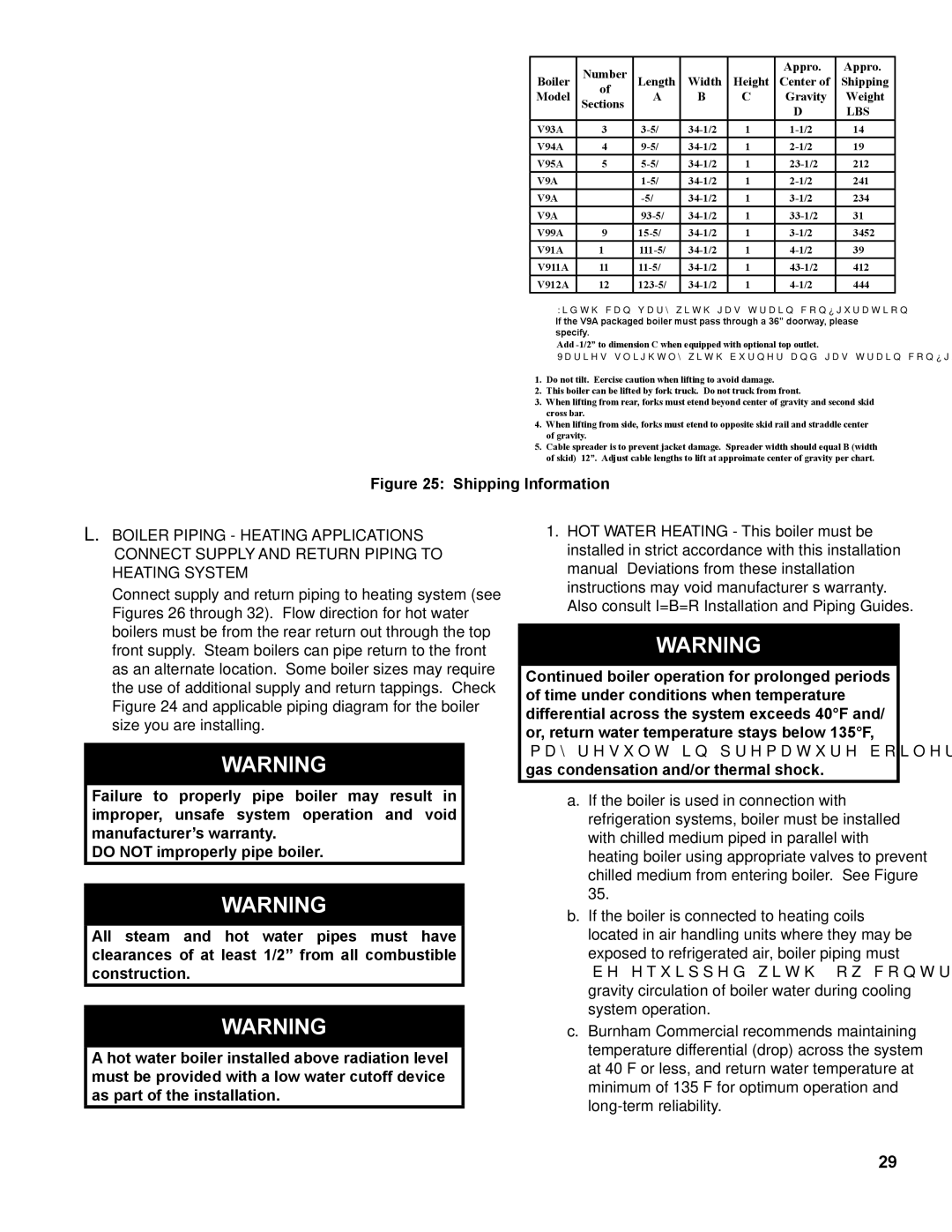
V9A specifications
Burnham V9A is a well-established model in the world of cast iron boilers, renowned for its efficiency and reliability in residential heating applications. As a part of Burnham's esteemed line of heating solutions, the V9A is designed to provide homeowners with consistent warmth while prioritizing fuel economy and ease of use.One of the defining features of the Burnham V9A is its durable cast iron construction. This robust material enables the boiler to withstand high temperatures and pressures, ensuring a long service life. The V9A is engineered with several sections that are joined together, allowing for easier maintenance and potential adaptability to various heating demands. The boiler's design also promotes excellent heat retention, which not only enhances performance but contributes to overall energy efficiency.
In terms of technology, the Burnham V9A stands out with its advanced combustion design. With an efficiency rating of up to 85%, this model maximizes the heat output while minimizing fuel consumption. The boiler is compatible with both natural gas and propane, providing flexibility for users to choose their preferred fuel source. Additionally, the V9A is designed to operate with a minimum of venting requirements, making installation simpler and more cost-effective.
The Burnham V9A also features a choice of various firing rates, allowing homeowners to select the optimal heating output for their specific needs. This versatility ensures that the boiler can be effectively sized for different home environments, making it a highly adaptable option for a broad range of residential settings.
Moreover, one key characteristic of the Burnham V9A is its user-friendly control systems. It comes equipped with reliable electronic ignition and offers options for outdoor reset controls, which enhance efficiency by adjusting the boiler's operation based on the outdoor temperature. This advanced control capability not only optimizes energy use but also enhances comfort levels in the home.
Overall, the Burnham V9A represents a balance of durability, efficiency, and modern convenience, making it a top choice for homeowners seeking a reliable heating solution. Its combination of cast iron construction, advanced technology, and user-friendly features solidify its reputation in the competitive market of heating systems, ensuring comfort and peace of mind for years to come.