Installing the 9Cx14 Chassis
|
|
|
| EPIM |
|
|
|
|
|
|
|
|
|
|
|
|
|
| STATUS |
|
|
|
|
|
|
|
|
|
|
|
|
|
| ALARM |
|
|
|
|
|
|
|
|
|
|
|
|
|
|
| COM 1 COM 2 |
|
|
|
|
| ENTER |
|
| |
|
|
|
|
|
|
|
|
|
|
|
|
| ||
ENVIRONMENTAL MODULE |
|
|
|
|
|
|
|
|
|
|
|
|
| |
1 | 2 | 3 | 4 | 5 | 6 | 7 | 8 | 9 | 10 | 11 | 12 | 13 | 14 |
|
|
|
|
|
|
|
|
|
|
|
|
|
| ALWAYS USE ESD | ESD WRIST STRAP |
|
|
|
|
|
|
|
|
|
|
|
|
| WRIST STRAP WHEN | GROUNDING |
|
|
|
|
|
|
|
|
|
|
|
|
| HANDLING MODULES | RECEPTACLE |
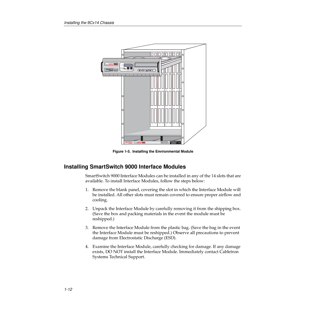
Figure 1-5. Installing the Environmental Module
Installing SmartSwitch 9000 Interface Modules
SmartSwitch 9000 Interface Modules can be installed in any of the 14 slots that are available. To install Interface Modules, follow the steps below:
1.Remove the blank panel, covering the slot in which the Interface Module will be installed. All other slots must remain covered to ensure proper airflow and cooling.
2.Unpack the Interface Module by carefully removing it from the shipping box. (Save the box and packing materials in the event the module must be reshipped.)
3.Remove the Interface Module from the plastic bag. (Save the bag in the event the Interface Module must be reshipped.) Observe all precautions to prevent damage from Electrostatic Discharge (ESD).
4.Examine the Interface Module, carefully checking for damage. If any damage exists, DO NOT install the Interface Module. Immediately contact Cabletron Systems Technical Support.