INSTALLATION
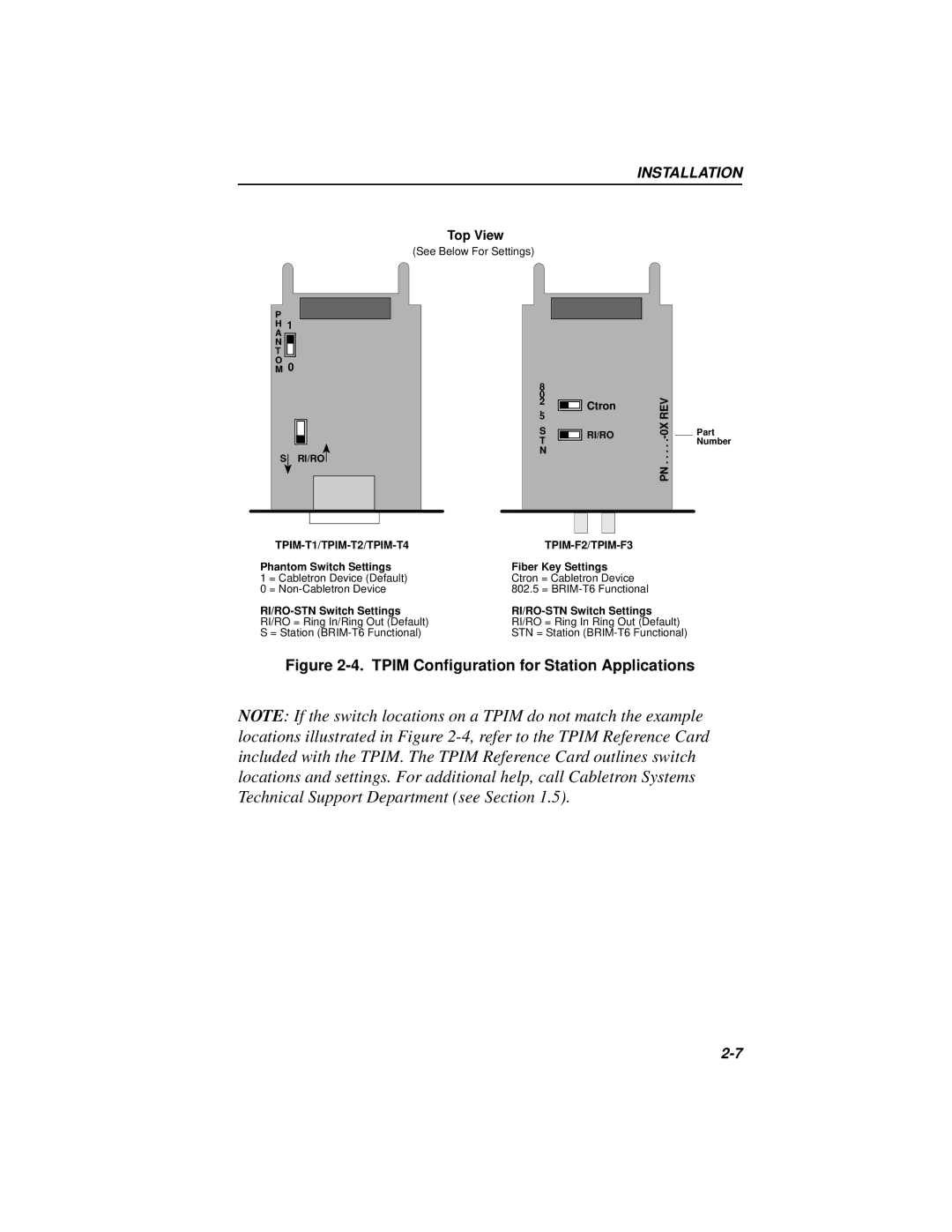
Top View
(See Below For Settings)
P
H1
A
N
T
OM 0
S ![]() RI/RO
RI/RO ![]()
TPIM-T1/TPIM-T2/TPIM-T4
Phantom Switch Settings
1 = Cabletron Device (Default)
0 =
RI/RO = Ring In/Ring Out (Default)
S = Station
8 |
|
|
|
|
|
|
|
|
|
|
|
0 |
|
|
|
|
|
|
|
| REV | ||
5 |
|
|
|
|
|
|
|
| |||
2 |
|
|
| Ctron |
|
|
| ||||
. |
|
|
|
|
| ||||||
|
|
|
|
| |||||||
S |
|
|
| RI/RO |
|
| |||||
T |
|
|
|
|
|
|
|
| . |
|
|
N |
|
|
|
|
|
|
| . |
|
| |
|
|
|
|
|
|
|
|
| PN . . | ||
|
|
|
|
|
|
|
|
|
|
|
|
|
|
|
|
|
|
|
|
|
|
|
|
|
|
|
|
|
|
|
|
|
|
|
|
TPIM-F2/TPIM-F3
Fiber Key Settings
Ctron = Cabletron Device
802.5 =
RI/RO = Ring In Ring Out (Default)
STN = Station
Part Number
Figure 2-4. TPIM Configuration for Station Applications
NOTE: If the switch locations on a TPIM do not match the example locations illustrated in Figure