3.Connecting the Adapter to your System
3.1.Connector Pinout
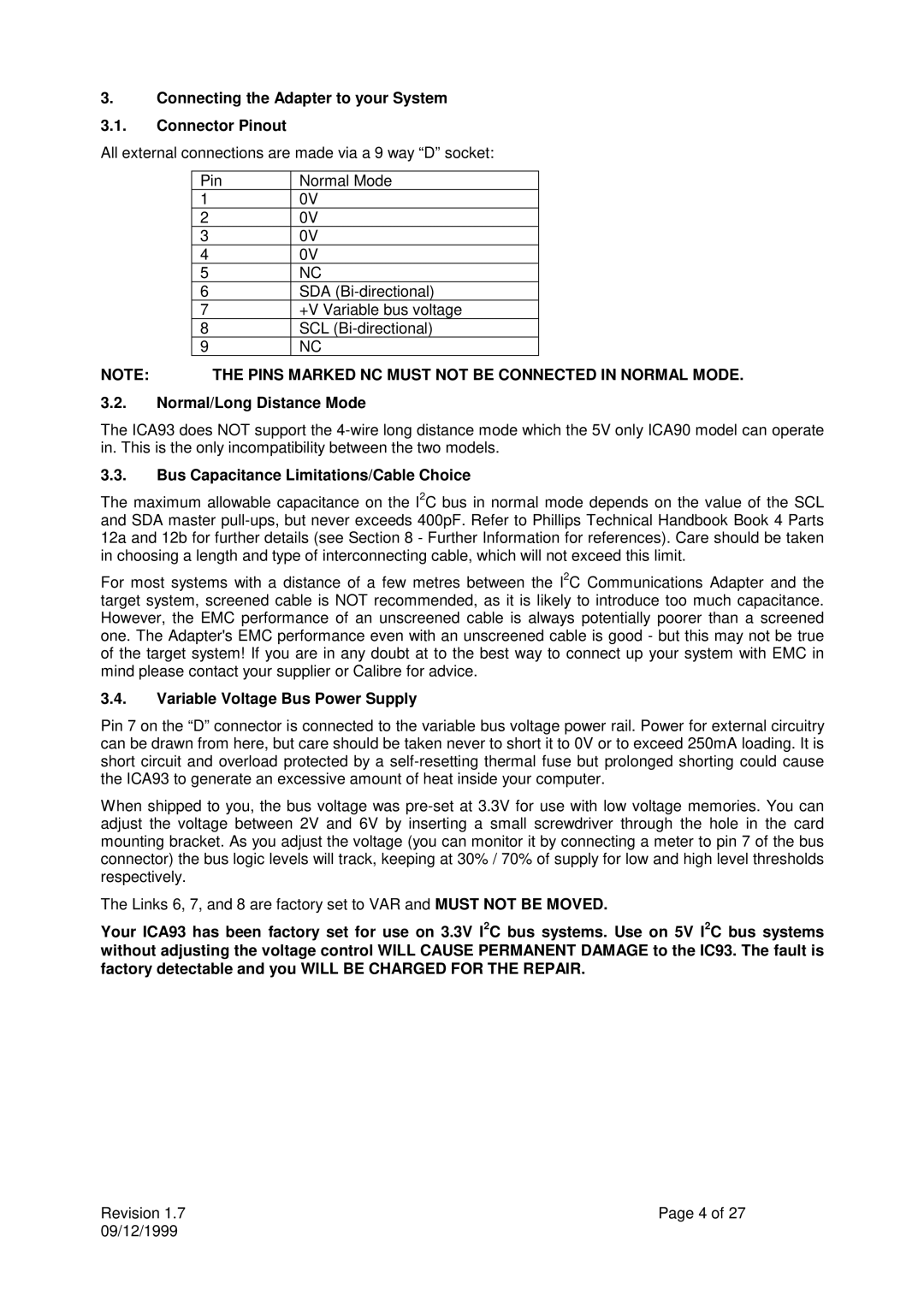
All external connections are made via a 9 way “D” socket:
| Pin | Normal Mode |
| |
| 1 |
| 0V |
|
| 2 |
| 0V |
|
| 3 |
| 0V |
|
| 4 |
| 0V |
|
| 5 |
| NC |
|
| 6 |
| SDA |
|
| 7 |
| +V Variable bus voltage |
|
| 8 |
| SCL |
|
| 9 |
| NC |
|
NOTE: | THE PINS MARKED NC MUST NOT BE CONNECTED IN NORMAL MODE. | |||
3.2.Normal/Long Distance Mode
The ICA93 does NOT support the
3.3.Bus Capacitance Limitations/Cable Choice
The maximum allowable capacitance on the I2C bus in normal mode depends on the value of the SCL and SDA master
For most systems with a distance of a few metres between the I2C Communications Adapter and the target system, screened cable is NOT recommended, as it is likely to introduce too much capacitance. However, the EMC performance of an unscreened cable is always potentially poorer than a screened one. The Adapter's EMC performance even with an unscreened cable is good - but this may not be true of the target system! If you are in any doubt at to the best way to connect up your system with EMC in mind please contact your supplier or Calibre for advice.
3.4.Variable Voltage Bus Power Supply
Pin 7 on the “D” connector is connected to the variable bus voltage power rail. Power for external circuitry can be drawn from here, but care should be taken never to short it to 0V or to exceed 250mA loading. It is short circuit and overload protected by a
When shipped to you, the bus voltage was
The Links 6, 7, and 8 are factory set to VAR and MUST NOT BE MOVED.
Your ICA93 has been factory set for use on 3.3V I2C bus systems. Use on 5V I2C bus systems without adjusting the voltage control WILL CAUSE PERMANENT DAMAGE to the IC93. The fault is factory detectable and you WILL BE CHARGED FOR THE REPAIR.
Revision 1.7 | Page 4 of 27 |
09/12/1999 |
|