OPTIONS | 5.1 E.U.I. (Extended User Interface) | |||||||
| ||||||||
| The E.U.I. slot contains the Rear XLR Panel and the Input Signal Parallel switch | |||||||
| as standard. Other input cards are available (See 5.1.3 Accessories) Always switch | |||||||
| off and unplug the VORTEX from mains, when working on the E.U.I. | |||||||
5.0 | The switches described below are not readily accessible and cannot be | |||||||
checked visually from the outside. To remove the E.U.I. unscrew the two Phillips | ||||||||
| ||||||||
| head screws at the left and right end of | |||||||
| E.U.I. To refit the E.U.I into the VORTEX, carefully insert the PCB in the | |||||||
| (left/right) and slide it in. | |||||||
| Don’t forget to replace the screws! | |||||||
| 5.1.1 Input Signal Parallel Switch | |||||||
| If you want to | |||||||
| change from Stereo to Mono using switch S1. Be careful when you do this! | |||||||
| (See section 3.7, Input Signal Chaining) | |||||||
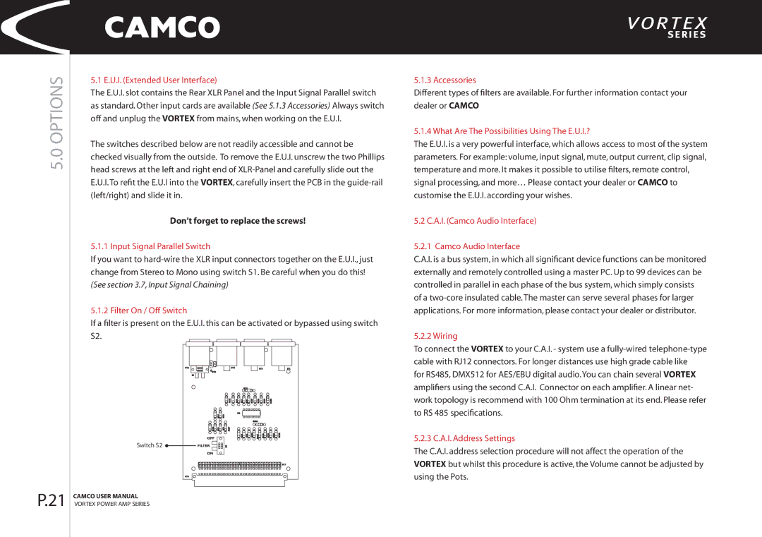
| 5.1.2 Filter On / Off Switch | |||||||
| If a filter is present on the E.U.I. this can be activated or bypassed using switch | |||||||
| S2. | |||||||
|
|
|
|
|
|
|
| |
|
|
|
|
|
|
|
| |
|
|
|
|
|
|
|
| |
Switch S2 ![]()
5.1.3 Accessories
Different types of filters are available. For further information contact your dealer or CAMCO
5.1.4 What Are The Possibilities Using The E.U.I.?
The E.U.I. is a very powerful interface, which allows access to most of the system parameters. For example: volume, input signal, mute, output current, clip signal, temperature and more. It makes it possible to utilise filters, remote control, signal processing, and more… Please contact your dealer or CAMCO to customise the E.U.I. according your wishes.
5.2 C.A.I. (Camco Audio Interface)
5.2.1 Camco Audio Interface
C.A.I. is a bus system, in which all significant device functions can be monitored externally and remotely controlled using a master PC. Up to 99 devices can be controlled in parallel in each phase of the bus system, which simply consists of a
5.2.2 Wiring
To connect the VORTEX to your C.A.I. - system use a
for RS485, DMX512 for AES/EBU digital audio.You can chain several VORTEX amplifiers using the second C.A.I. Connector on each amplifier. A linear net- work topology is recommend with 100 Ohm termination at its end. Please refer to RS 485 specifications.
5.2.3 C.A.I. Address Settings
The C.A.I. address selection procedure will not affect the operation of the VORTEX but whilst this procedure is active, the Volume cannot be adjusted by using the Pots.
P.21 | CAMCO USER MANUAL |
VORTEX POWER AMP SERIES |