Contents
Page
For Vortex Models 2.6, 4
Explanation of Symbols
Please Refer ALL Servicing to
Safety
Safety Check
Replacement Parts
Servicing
EC Declaration of Conformity
Manufacturers Name
Manufacturers Address
Declares that the product with the model name
Contents
Welcome to Camco
Welcome
Unpacking
Amplifier
Facilities
Vortex The Rear
Installation
On/off Switch
Precautions
Mounting
Cooling
Wiring Speakon Connection
Ground Lift
2 E.U.I. and XLR Connection Mode Indicators
Mode Switch
Parallel-Mono Operation
Stereo Operation
Bridge-Mono Operation One-channel mono bridged operation
Input Signal Chaining
Controls Volume Control
Limiter Switch
Operation
Gain Selector
Indicators 1 On / Failure Indicators
Signal Indicators
Clip / Output Current Indicators
See 4.4.1,Clip Limiter and 4.4.3, Speaker Protect Limiter
To disable the Clip Limiter, see 4.2.3, Limiter Switch
Power Amp Over Current Protection
Power Amp Thermal Protection
DC Servo
Mains Protection Inrush Current Limitation
Vortex Filter Assembly
Filter Cleaning
Fans
See .7, Input Signal Chaining
To Activate CAI Address Selection Procedure
CAI Status Indicator
Overview Or Remote Controls CAI CAI allows
Options
Troubleshooting
On LED Flashing Sequences Examples of LED Sequences
Problem No Sound or Sound is too Low
Problem No Sound
Problem No Channel Separation
Problem Distorted Sound
Problem Music Sounds Frequency Filtered
Problem Hiss
Problem Squeals and Feedback
Specification
Output Power
Signal to Noise-Ratio
Power Consumtion @ 230 Typical Max2
Subject to technical alterations without prior notice
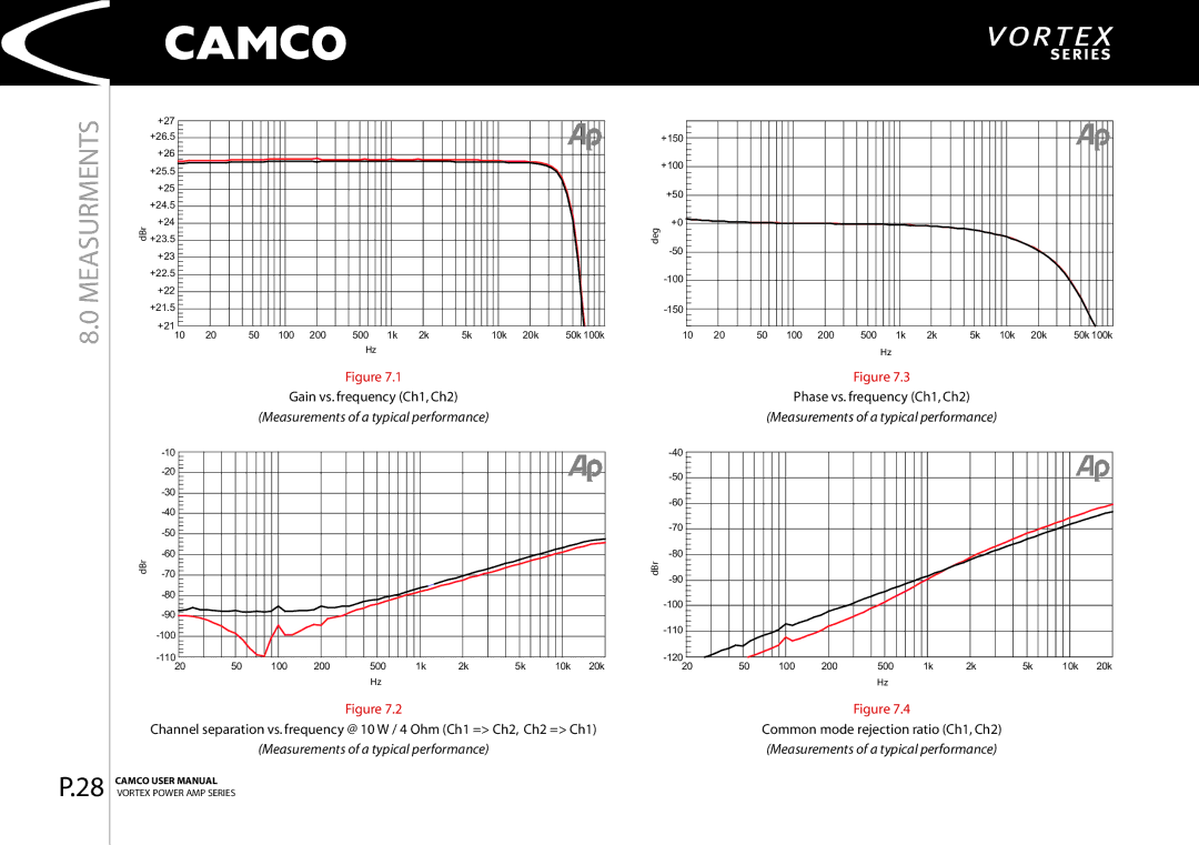
Measurments
Measurements of a typical performance
THD+N @ 1 kHz, 4 Ohm load vs. input voltage Ch1, Ch2
Ohms Ch1, Ch2 Measurements of a typical performance
Ch1, Ch2 Measurements of a typical performance
1257
Vortex 2.6 Measurements of a typical performance
Warranty Information
Expired Warranty
Nature Of Problem
Owner’s Information Company Name Contact
Shipping Address
Mailing Address
Company Information
Internet