Operating Instructions
DG472500DI
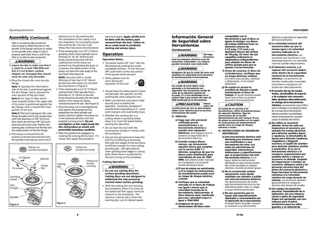
Assembly (Continued)
little or no
4.Inspect the disc to make sure that it is rated for at least 7000 RPM and that it is not broken, cracked, chipped, etc. Damaged discs should never be used, only discarded.
5.Place the chosen disc onto the disc flange.
Note 1: Typically the information side of the disc in positioned against the disc flange, that is, toward the main portion of the tool itself. Note 2: For Type 27 discs which have recessed centers, the upper side of its center is positioned against the disc flange, that is, toward the main portion of the tool.
Note 3: This tool is equipped with a disc flange shoulder which only accepts discs with hole diameters of 7/8" [22.2mm].
Discs which do not have 7/8" [22.2mm] bores should not be used. Position the working disc so that its hole fits flat over the raised portion of the disc flange.
6.The clamp nut should then be properly oriented and screwed onto the spindle clockwise by hand until it
| Clamp nut |
|
| turned incorrectly | |
To Tighten | Wrench | |
|
| |
|
| Clamp |
To Loosen |
| Nut |
Grinding |
|
|
wheel |
|
|
Disc |
| Guard |
|
| |
Flange |
|
|
Spindle |
|
|
Figure 4 |
|
|
bottoms out on the working disc. The orientation of this clamp nut is very important, for to properly secure the working disc, the user must follow the instructions directly below:
•If the working disc is a 4 1/2" [115mm] grinding wheel, these typically have a thickness
NOTE: Any discs with a center thickness of less than 0.16" [4mm] should have the clamp nut oriented like that shown in Figure 5
•If the working disc is a 4 1/2" [115mm] cutting wheel, these typically have a thickness of .12" [3mm] or less and thusly should be secured with the raised portion of the clamp nut facing outward toward the user. (See Figure 5)
•Once the clamp nut is
7.With the spindle lock engaged, try rotating the working disc by hand. If it moves, then repeat the procedure
| Clamp nut |
| turned incorrectly |
| Clamp nut |
Cutting | turned |
disc | correctly |
Figure 5
starting at step 5. Again, all this is to be done with the battery pack removed from the tool. Failure to do so could result in accidental starting and serious injury.
Operation
Operation Notes:
•The power switch will “lock” into the ON position by pushing the switch completely forward. To turn the tool OFF, push down on the rear portion of the power switch actuator.
•Safety glasses must be worn during the
operation of this tool.
•Always keep the safety guard in place and between the operator and the working disc when using this tool.
•Make sure that the work piece is held securely prior to starting the operation. Clamp the workpiece if possible before operating on it. Loose work may spin and cause bodily injury.
•Whether the working disc is a cutting wheel or grinding wheel, allow it to reach full speed before starting the operation.
•Do not start the tool with the working disc already in contact with the workpiece.
•Use just enough pressure to keep this tool from chattering or bouncing. Normally the weight of the tool alone is sufficient enough for most cutting/ grinding jobs. Use light pressure when grinding loose edges or cutting bolts where there is a potential for the tool to snag on the workpiece.
Cutting Operation
•Do not use cutting discs for surface grinding operations. Cutting discs are not designed to withstand the side pressures exerted when surface grinding.
•With the cutting disc not touching the workpiece, allow it to come up full speed and then apply minimum pressure to the workpiece. The optimum cutting rate is when the working disc is at its highest speed.
Información General de Seguridad sobre Herramientas
(Continuación)
No haga funcionar
esta herramienta eléctrica cerca de materiales inflamables. Las chispas pueden incendiar esos materiales.
Asegúrese de que la rueda de corte esté ajustada con seguridad antes de poner en funcionamiento la herramienta.
Las ruedas de corte deben estar ajustadas a la herramienta con seguridad. Use únicamente ruedas de corte de un diámetro máximo de
4,5 pulg. (11,5 cm) clasificadas en el mismo valor o por encima del valor de RPM clasificado de la herramienta.
Nunca cubra las
ventilaciones de aire ya que siempre deben estar abiertas para el correcto enfriamiento del motor.
5)SERVICIO
a)Haga que sólo personal calificado preste mantenimiento a su herramienta eléctrica y usando sólo repuestos idénticos. Esto asegura que se preserva la seguridad de la herramienta eléctrica.
b)Cuando compre discos nuevos, use únicamente aquellos discos que cumplan con la norma ANSI 7.1. Además, asegúrese de que los discos están clasificados para velocidades de más de 7000 RPM. Esto debería estar marcado en el empaque o en la parte frontal del propio disco.
c)El uso de piezas no autorizadas o el no seguir las instrucciones de mantenimiento puede crear un riesgo de choque eléctrico o lesión.
d)Verifique que la velocidad marcada en el disco de trabajo sea igual o mayor que la velocidad marcada de la herramienta, básicamente, el disco debería estar clasificado para una velocidad mayor o igual a 7000 RPM.
e)Asegúrese de que las dimensiones del disco sean
compatibles con la herramienta y que el disco se ajuste al vástago. Los discos de trabajo deberían tener un diámetro externo de
4 1/2 pulg. (115 mm) y un diámetro interno del orificio de 7/8 pulg. (22 mm). No use casquillos reductores ni adaptadores independientes para adaptar los discos de orificio grande para que se ajusten a la herramienta.
f)Antes de conectar el disco de corte/abrasivo, verifique que no tenga defectos visibles.
Si el disco está partido, astillado o deformado, no lo instale. Deséchelo.
g)No ajuste en exceso la arandela de fijación cuando instale/ajuste el disco de trabajo. El ajuste excesivo puede hacer que el disco se quiebre durante el funcionamiento.
Al realizarle un servicio a las herramientas, utilice únicamente piezas de repuesto idénticas. Siga las instrucciones de la sección Mantenimiento de este manual. El uso de piezas no autorizadas o el no seguir las instrucciones de mantenimiento puede crear un riesgo de choque eléctrico o lesión.
6)INSTRUCCIONES DE SEGURIDAD ADICIONALES
a)Esta herramienta eléctrica está diseñada para funcionar como una rectificadora o una herramienta de corte. Lea todas las advertencias de seguridad, instrucciones, ilustraciones y especificaciones que se proporcionan con esta herramienta eléctrica. El no seguir todas las instrucciones detalladas en este manual puede dar como resultado un choque eléctrico, incendio y/o lesión grave.
b)No se recomienda realizar operaciones como lijado, cepillado con alambre o pulido con esta herramienta eléctrica. Las operaciones para las cuales esta herramienta eléctrica no fue diseñada pueden crear un riesgo y causar lesiones personales.
c)No use accesorios que no hayan sido específicamente diseñados y recomendados por el fabricante de la herramienta. El simple hecho de poder conectar un accesorio a su herramienta
eléctrica no garantiza la seguridad del funcionamiento.
d)La velocidad nominal del accesorio debe ser por lo menos igual a la velocidad máxima indicada en la herramienta eléctrica. Los accesorios que funcionen a una velocidad superior a la velocidad nominal pueden desprenderse.
e)El diámetro exterior y el espesor del accesorio deben estar dentro de la capacidad nominal de la herramienta eléctrica. Los accesorios de tamaño inadecuado no pueden controlarse o equiparse con protección adecuadamente.
f)El tamaño del eje de ruedas, bridas, almohadillas de soporte o de cualquier otro accesorio debe ajustarse adecuadamente al vástago de la herramienta eléctrica. Los accesorios cuyo orificio para el vástago no se ajusta la pieza de montaje de la herramienta eléctrica pierden la estabilidad, vibran excesivamente y pueden causar la pérdida del control.
g)No utilice un accesorio dañado. Antes de cada uso inspeccione el accesorio, por ejemplo las ruedas abrasivas para detectar posibles lascas y rajaduras, la almohadilla de apoyo para detectar rajaduras, rasgaduras o desgaste excesivo, el cepillo de alambre para detectar alambres sueltos o quebrados. Si se cae la herramienta eléctrica o el accesorio, inspecciónelos por posibles daños o instale un accesorio no dañado. Después de inspeccionar e instalar un accesorio, ubíquese usted y las personas cercanas lejos del plano del accesorio giratorio y haga funcionar la herramienta mecánica a la velocidad máxima sin carga durante un minuto. Los accesorios dañados generalmente se romperán durante este tiempo de prueba.
h)Use equipo de protección personal. Dependiendo de la aplicación, use una máscara, careta o gafas de seguridad. Según sea apropiado, use una máscara para el polvo, protectores para los oídos, guantes y un delantal de
8 | 29 Sp |