![]()
![]()
![]()
![]() ... the analog plusTM compa
... the analog plusTM compa
EXAR Corporation 48720 Kato Road, Fremont, CA 94538 Phone | ||||||||||||||
PRELIMINARY |
|
|
|
|
|
|
|
|
|
|
|
|
| |
|
| DVDD | VREF+ |
| DB7:0 | DGND | AVDD | AGND |
| SYNCH CLAMP | ADCCLK |
| ||
|
|
|
|
| 8 |
|
|
|
|
|
|
|
|
|
|
|
|
|
| DATA I/O | PORT |
|
|
|
|
|
|
| CONTROL LOGIC |
|
| Power Down |
|
|
|
| Power Down |
|
|
| TIMING & | |||
| AVDD |
|
| 12 RL ADC |
| AGND |
|
| ||||||
|
|
| VRT |
|
|
| VRB |
|
|
|
|
|
|
|
|
|
|
|
| PGA |
| 6 G<5:0> | R G B | 8 O<7:0> | REGISTERS | R G B | |||
| VBG |
|
| BUFFER |
|
|
|
|
|
|
| CIS/CCD |
|
|
Circuit for CANON |
|
| + | _ |
| DCREF |
|
|
| AGND |
|
|
| |
|
| DCREF | INT/EXT V |
|
|
|
|
|
| |||||
CIS |
| V |
|
|
|
|
| CIS | ||||||
|
|
|
|
|
| VRT CCD | ||||||||
Biasing |
|
|
|
|
|
| CLP |
| DC/AC |
|
|
|
|
|
|
| S/H & |
|
|
|
|
|
|
|
|
|
|
| |
|
| CLAMP |
|
|
|
|
|
|
|
|
|
|
| |
|
| RED | GRN | BLU |
| VDCEXT |
|
|
|
|
|
|
| |
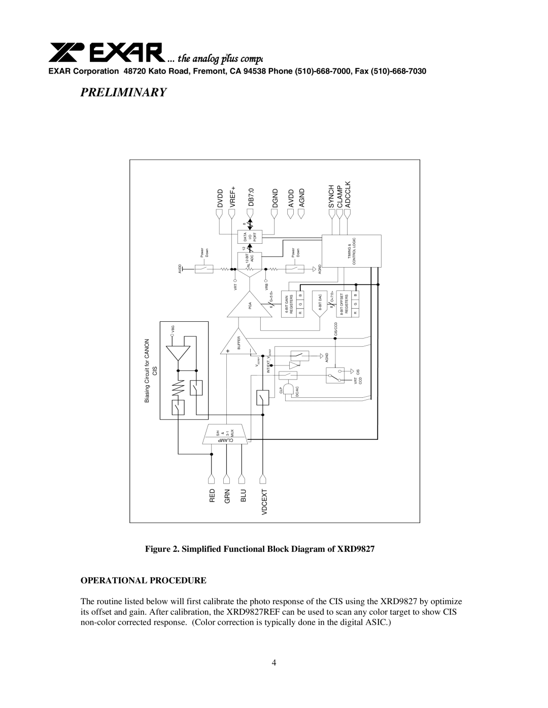
Figure 2. Simplified Functional Block Diagram of XRD9827
OPERATIONAL PROCEDURE
The routine listed below will first calibrate the photo response of the CIS using the XRD9827 by optimize its offset and gain. After calibration, the XRD9827REF can be used to scan any color target to show CIS
4