INSTALLATION
STEP 1
Unpack Unit
Move to final location. Remove carton taking care not to damage unit.
Inspect Equipment
File claim with shipping company prior to installation if shipment is damaged or incomplete. Locate unit rating plate on unit corner panel. It contains information needed to properly install unit. Check rating plate to be sure unit matches job specifications.
STEP 2 —Install on a Solid, Level Mounting Pad
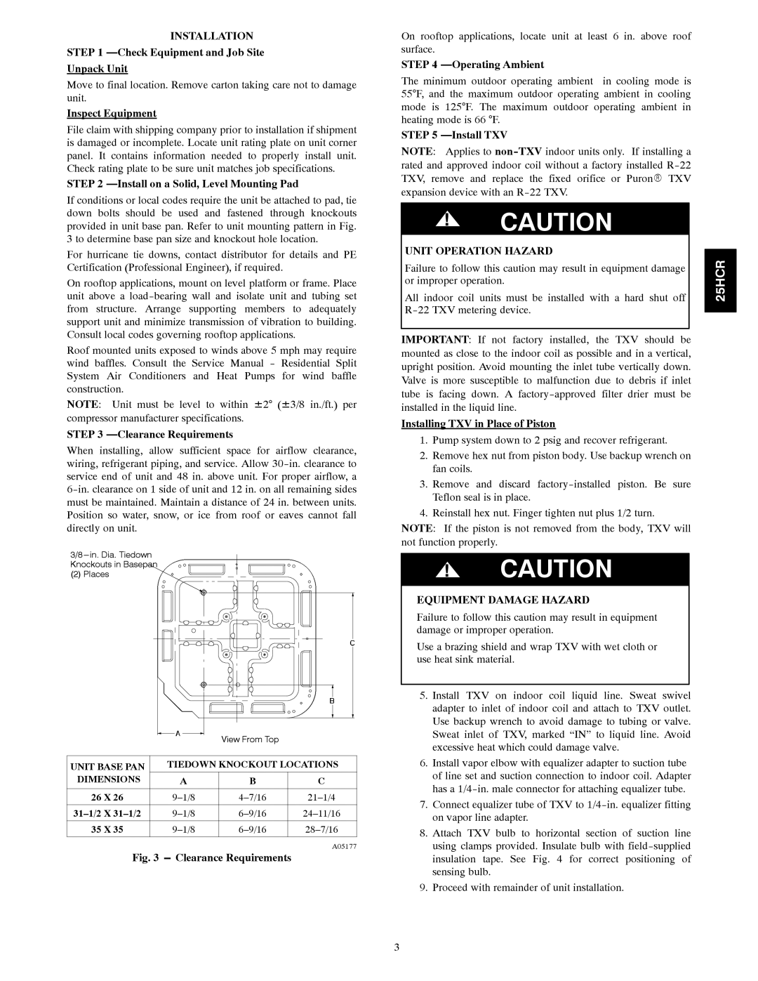
If conditions or local codes require the unit be attached to pad, tie down bolts should be used and fastened through knockouts provided in unit base pan. Refer to unit mounting pattern in Fig. 3 to determine base pan size and knockout hole location.
For hurricane tie downs, contact distributor for details and PE Certification (Professional Engineer), if required.
On rooftop applications, mount on level platform or frame. Place unit above a
Roof mounted units exposed to winds above 5 mph may require wind baffles. Consult the Service Manual - Residential Split System Air Conditioners and Heat Pumps for wind baffle construction.
NOTE: Unit must be level to within ±2° (±3/8 in./ft.) per compressor manufacturer specifications.
STEP 3 —Clearance Requirements
When installing, allow sufficient space for airflow clearance, wiring, refrigerant piping, and service. Allow
3/8
Knockouts in Basepan
(2) Places
|
| View From Top |
|
|
|
|
|
UNIT BASE PAN | TIEDOWN KNOCKOUT LOCATIONS | ||
DIMENSIONS | A | B | C |
|
|
|
|
26 X 26 | |||
|
|
|
|
35 X 35 | |||
|
|
|
|
A05177
Fig. 3 --- Clearance Requirements
On rooftop applications, locate unit at least 6 in. above roof surface.
STEP 4 —Operating Ambient
The minimum outdoor operating ambient in cooling mode is 55°F, and the maximum outdoor operating ambient in cooling mode is 125°F. The maximum outdoor operating ambient in heating mode is 66 °F.
STEP 5
NOTE: Applies to
!CAUTION
UNIT OPERATION HAZARD
Failure to follow this caution may result in equipment damage or improper operation.
All indoor coil units must be installed with a hard shut off
IMPORTANT: If not factory installed, the TXV should be mounted as close to the indoor coil as possible and in a vertical, upright position. Avoid mounting the inlet tube vertically down. Valve is more susceptible to malfunction due to debris if inlet tube is facing down. A
Installing TXV in Place of Piston
1.Pump system down to 2 psig and recover refrigerant.
2.Remove hex nut from piston body. Use backup wrench on fan coils.
3.Remove and discard
4.Reinstall hex nut. Finger tighten nut plus 1/2 turn. NOTE: If the piston is not removed from the body, TXV will not function properly.
!CAUTION
EQUIPMENT DAMAGE HAZARD
Failure to follow this caution may result in equipment damage or improper operation.
Use a brazing shield and wrap TXV with wet cloth or use heat sink material.
5.Install TXV on indoor coil liquid line. Sweat swivel adapter to inlet of indoor coil and attach to TXV outlet. Use backup wrench to avoid damage to tubing or valve. Sweat inlet of TXV, marked “IN” to liquid line. Avoid excessive heat which could damage valve.
6.Install vapor elbow with equalizer adapter to suction tube of line set and suction connection to indoor coil. Adapter has a
7.Connect equalizer tube of TXV to
8.Attach TXV bulb to horizontal section of suction line using clamps provided. Insulate bulb with
9.Proceed with remainder of unit installation.
25HCR
3