TB4
REMOTE
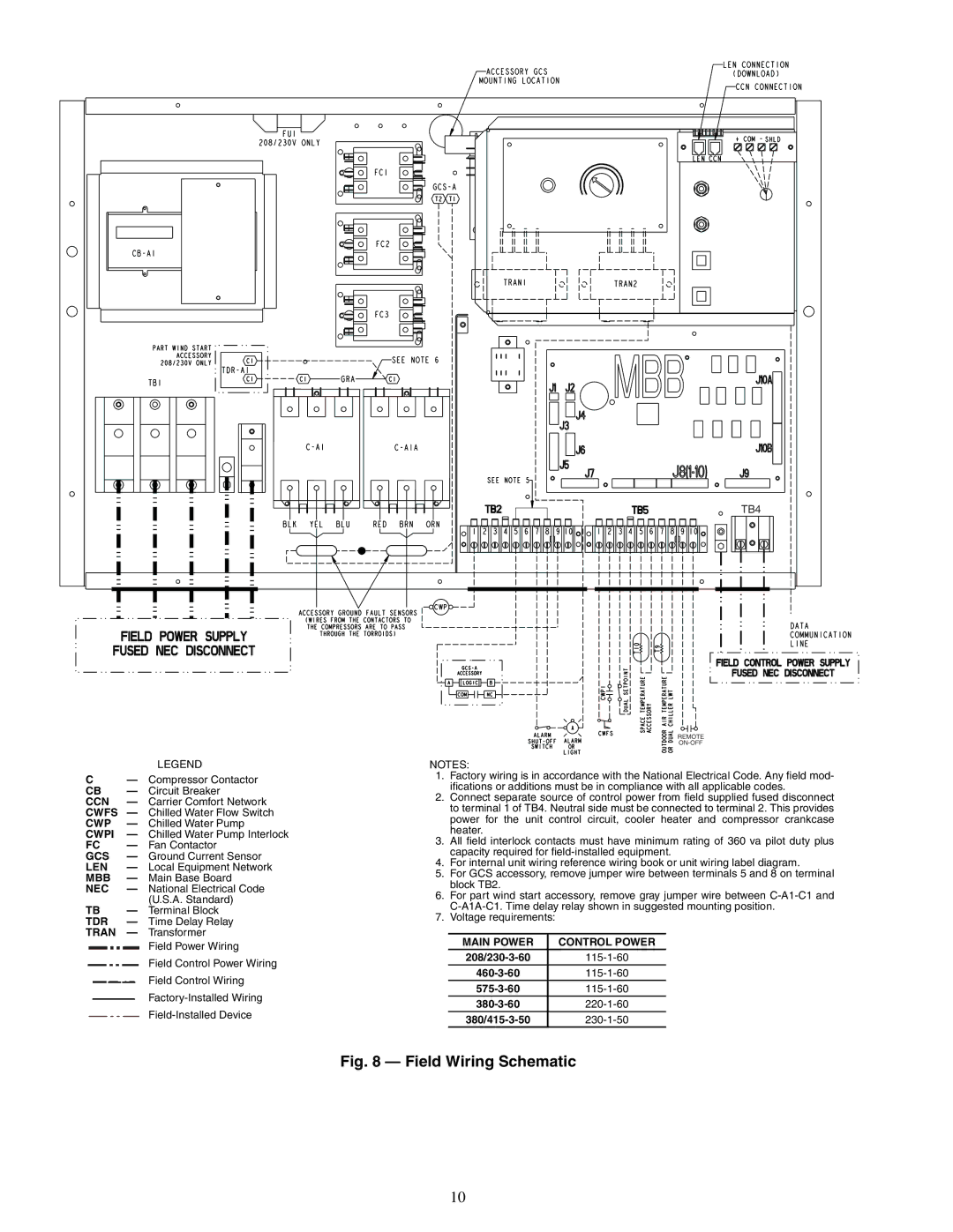
LEGEND
C— Compressor Contactor
CB — Circuit Breaker
CCN — Carrier Comfort Network CWFS — Chilled Water Flow Switch CWP — Chilled Water Pump
CWPI — Chilled Water Pump Interlock
FC — Fan Contactor
GCS — Ground Current Sensor LEN — Local Equipment Network MBB — Main Base Board
NEC — National Electrical Code (U.S.A. Standard)
TB — Terminal Block TDR — Time Delay Relay TRAN — Transformer
Field Power Wiring
Field Control Power Wiring
Field Control Wiring
NOTES:
1.Factory wiring is in accordance with the National Electrical Code. Any field mod- ifications or additions must be in compliance with all applicable codes.
2.Connect separate source of control power from field supplied fused disconnect to terminal 1 of TB4. Neutral side must be connected to terminal 2. This provides power for the unit control circuit, cooler heater and compressor crankcase heater.
3.All field interlock contacts must have minimum rating of 360 va pilot duty plus capacity required for
4.For internal unit wiring reference wiring book or unit wiring label diagram.
5.For GCS accessory, remove jumper wire between terminals 5 and 8 on terminal block TB2.
6.For part wind start accessory, remove gray jumper wire between
7.Voltage requirements:
MAIN POWER | CONTROL POWER |
Fig. 8 — Field Wiring Schematic
10