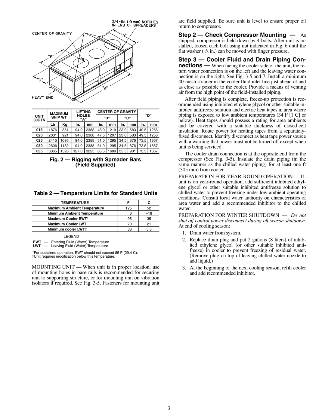
| MAXIMUM | LIFTING | CENTER OF GRAVITY |
|
| |||||
UNIT | SHIP WT | HOLES | “B” | “C” | “D” | |||||
30GTN | “A” |
|
| |||||||
|
|
|
|
|
|
|
| |||
| Lb | Kg | in. | mm | in. | mm | in. | mm | in. | mm |
015 | 1876 | 851 | 94.0 | 2388 | 48.0 | 1219 | 23.0 | 583 | 49.5 | 1256 |
020 | 2031 | 921 | 94.0 | 2388 | 47.5 | 1207 | 23.0 | 583 | 49.5 | 1256 |
025 | 2415 | 1095 | 94.0 | 2388 | 51.0 | 1295 | 34.5 | 876 | 73.5 | 1867 |
030 | 2606 | 1182 | 94.0 | 2388 | 51.0 | 1295 | 34.5 | 876 | 73.5 | 1867 |
035 | 3365 | 1526 | 127.0 | 3225 | 66.5 | 1689 | 35.5 | 901 | 73.5 | 1867 |
Fig. 2 — Rigging with Spreader Bars
(Field Supplied)
Table 2 — Temperature Limits for Standard Units
TEMPERATURE | F | C |
Maximum Ambient Temperature | 125 | 52 |
Minimum Ambient Temperature | 0 | |
Maximum Cooler EWT* | 95 | 35 |
Maximum Cooler LWT | 70 | 21 |
Minimum cooler LWT† | 38 | 3.3 |
LEGEND |
|
|
EWT — Entering Fluid (Water) Temperature
LWT — Leaving Fluid (Water) Temperature
*For sustained operation, EWT should not exceed 85 F (29.4 C). †Unit requires modification below this temperature.
MOUNTING UNIT — When unit is in proper location, use of mounting holes in base rails is recommended for securing unit to supporting structure, or for mounting unit on vibration isolators if required. See Fig.
are field supplied. Be sure unit is level to ensure proper oil return to compressor.
Step 2 — Check Compressor Mounting — As shipped, compressor is held down by 4 bolts. After unit is in- stalled, loosen each bolt using nut indicated in Fig. 6 until the flat washer (3/8 in.) can be moved with finger pressure.
Step 3 — Cooler Fluid and Drain Piping Con- nections — When facing the cooler side of the unit, the re- turn water connection is on the left and the leaving water con- nection is on the right. See Fig.
After field piping is complete,
The cooler drain connection is at the opposite end from the compressor (See Fig.
PREPARATION FOR
PREPARATION FOR WINTER SHUTDOWN — Do not shut off control power disconnect during
1.Drain water from system.
2.Replace drain plug and put 2 gallons (8 liters) of inhib- ited ethylene glycol (or other suitable inhibited anti- freeze) in cooler to prevent freezing of residual water. (Remove plug on top of leaving chilled water nozzle to add liquid.)
3.At the beginning of the next cooling season, refill cooler and add recommended inhibitor.
3