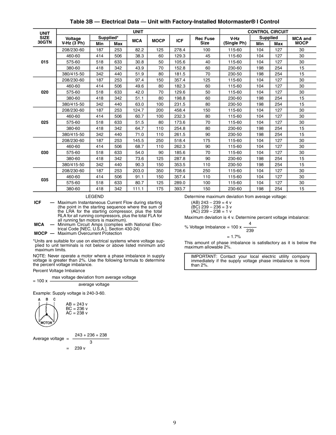
Table 3B — Electrical Data — Unit with
UNIT |
|
|
| UNIT |
|
|
|
| CONTROL CIRCUIT |
| |||
SIZE | Voltage | Supplied* | MCA | MOCP | ICF | Rec Fuse |
| Supplied |
| MCA and | |||
30GTN |
| Min | Max | Size | (Single Ph) |
| Min | Max |
| MOCP | |||
|
|
|
|
| |||||||||
| 187 | 253 | 82.2 | 125 | 278.4 | 100 |
| 104 | 127 |
| 30 | ||
| 414 | 506 | 38.3 | 60 | 129.3 | 45 |
| 104 | 127 |
| 30 | ||
015 | 518 | 633 | 30.8 | 50 | 105.6 | 40 |
| 104 | 127 |
| 30 | ||
| 418 | 342 | 43.9 | 70 | 152.8 | 60 |
| 198 | 254 |
| 15 | ||
| 342 | 440 | 51.9 | 80 | 181.5 | 70 |
| 198 | 254 |
| 15 | ||
| 187 | 253 | 97.4 | 150 | 357.4 | 125 |
| 104 | 127 |
| 30 | ||
| 414 | 506 | 49.6 | 80 | 182.3 | 60 |
| 104 | 127 |
| 30 | ||
020 | 518 | 633 | 42.0 | 70 | 129.6 | 50 |
| 104 | 127 |
| 30 | ||
| 418 | 342 | 51.1 | 80 | 198.8 | 60 |
| 198 | 254 |
| 15 | ||
| 342 | 440 | 63.0 | 100 | 231.5 | 80 |
| 198 | 254 |
| 15 | ||
| 187 | 253 | 124.7 | 200 | 458.4 | 150 |
| 104 | 127 |
| 30 | ||
| 414 | 506 | 60.7 | 100 | 232.3 | 80 |
| 104 | 127 |
| 30 | ||
025 | 518 | 633 | 51.5 | 80 | 173.6 | 70 |
| 104 | 127 |
| 30 | ||
| 418 | 342 | 64.7 | 110 | 254.8 | 80 |
| 198 | 254 |
| 15 | ||
| 342 | 440 | 71.0 | 110 | 261.5 | 90 |
| 198 | 254 |
| 15 | ||
| 187 | 253 | 145.5 | 250 | 518.4 | 175 |
| 104 | 127 |
| 30 | ||
| 414 | 506 | 68.7 | 110 | 262.3 | 90 |
| 104 | 127 |
| 30 | ||
030 | 518 | 633 | 54.0 | 90 | 185.6 | 70 |
| 104 | 127 |
| 30 | ||
| 418 | 342 | 73.6 | 125 | 287.8 | 90 |
| 198 | 254 |
| 15 | ||
| 342 | 440 | 90.3 | 150 | 353.5 | 110 |
| 198 | 254 |
| 15 | ||
| 187 | 253 | 203.0 | 350 | 708.6 | 250 |
| 104 | 127 |
| 30 | ||
035 | 414 | 506 | 91.1 | 150 | 357.4 | 110 |
| 104 | 127 |
| 30 | ||
518 | 633 | 80.7 | 125 | 289.0 | 100 |
| 104 | 127 |
| 30 | |||
|
|
| |||||||||||
| 418 | 342 | 111.1 | 175 | 393.7 | 150 |
| 198 | 254 |
| 15 | ||
LEGEND
ICF — Maximum Instantaneous Current Flow during starting (the point in the starting sequence where the sum of the LRA for the starting compressor, plus the total RLA for all running compressors, plus the total FLA for all running fan motors is maximum).
MCA — Minimum Circuit Amps (complies with National Elec- trical Code [NEC, U.S.A.], Section
MOCP — Maximum Overcurrent Protection
*Units are suitable for use on electrical systems where voltage sup- plied to unit terminals is not below or above listed minimum and maximum limits.
NOTE: Never operate a motor where a phase imbalance in supply voltage is greater than 2%. Use the following formula to determine the percent voltage imbalance.
Percent Voltage Imbalance
max voltage deviation from average voltage
= 100 x
average voltage
Determine maximum deviation from average voltage:
(AB) 243 – 239 = 4 v (BC) 239 – 236 = 3 v (AC) 239 – 238 = 1 v
Maximum deviation is 4 v. Determine percent voltage imbalance:
4
% Voltage Imbalance = 100 x
239
= 1.7%
This amount of phase imbalance is satisfactory as it is below the maximum allowable 2%.
IMPORTANT: Contact your local electric utility company immediately if the supply voltage phase imbalance is more than 2%.
Example: Supply voltage is
AB = 243 v
BC = 236 v
AC = 238 v
243 + 236 + 238
Average voltage =
3
=239 v
9