providing electrical potential to second heater sequencer (if used). If outdoor temperature falls below setting of outdoor thermostat (field-installed option), contacts close to complete circuit and bring on second bank of supplemental electric heat.

When thermostat is satisfied, its contacts open, de-energizing contactor and sequencer. All heaters and motors should stop.

Quiet Shift

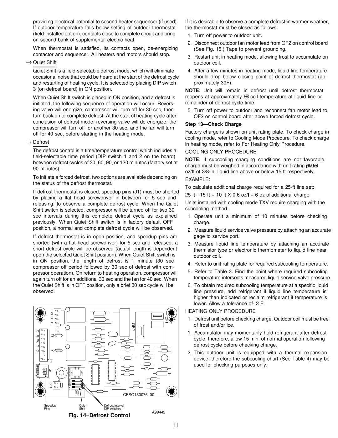
Quiet Shift is a field-selectable defrost mode, which will eliminate occasional noise that could be heard at the start of the defrost cycle and restarting of heating cycle. It is selected by placing DIP switch 3 (on defrost board) in ON position.

When Quiet Shift switch is placed in ON position, and a defrost is initiated, the following sequence of operation will occur. Revers- ing valve will energize, compressor will turn off for 30 sec, then turn back on to complete defrost. At the start of heating cycle after conclusion of defrost mode, reversing valve will de-energize, the compressor will turn off for another 30 sec, and the fan will turn off for 40 sec, before starting in the heating mode.

Defrost

The defrost control is a time/temperature control which includes a field-selectable time period (DIP switch 1 and 2 on the board) between defrost cycles of 30, 60, 90, or 120 minutes (factory set at 90 minutes).

To initiate a forced defrost, two options are available depending on the status of the defrost thermostat.

If defrost thermostat is closed, speedup pins (J1) must be shorted by placing a flat head screwdriver in between for 5 sec and releasing, to observe a complete defrost cycle. When the Quiet Shift switch is selected, compressor will be turned off for two 30 sec intervals during this complete defrost cycle as explained previously. When Quiet Shift switch is in factory default OFF position, a normal and complete defrost cycle will be observed.

If defrost thermostat is in open position, and speedup pins are shorted (with a flat head screwdriver) for 5 sec and released, a short defrost cycle will be observed (actual length is dependent upon the selected Quiet Shift position). When Quiet Shift switch is in ON position, the length of defrost is 1 minute (30 sec compressor off period followed by 30 sec of defrost with com- pressor operation). On return to heating operation, compressor will again turn off for an additional 30 sec and the fan for 40 sec. When the Quiet Shift is in OFF position, only a brief 30 sec cycle will be observed.

If it is desirable to observe a complete defrost in warmer weather, the thermostat must be closed as follows:

1.Turn off power to outdoor unit.

2.Disconnect outdoor fan motor lead from OF2 on control board (See Fig. 15.) Tape to prevent grounding.

3.Restart unit in heating mode, allowing frost to accumulate on outdoor coil.

4.After a few minutes in heating mode, liquid line temperature should drop below closing point of defrost thermostat (ap- proximately 30°F).

NOTE: Unit will remain in defrost until defrost thermostat reopens at approximately 80°F coil temperature at liquid line or remainder of defrost cycle time.

5.Turn off power to outdoor and reconnect fan motor lead to OF2 on control board after above forced defrost cycle.

Step 13—Check Charge

Factory charge is shown on unit rating plate. To check charge in cooling mode, refer to Cooling Mode Procedure. To check charge in heating mode, refer to For Heating Only Procedure.

COOLING ONLY PROCEDURE

NOTE: If subcooling charging conditions are not favorable, charge must be weighed in accordance with unit rating plate ± 0.6 oz/ft of 3/8-in. liquid line above or below 15 ft respectively.

EXAMPLE:

To calculate additional charge required for a 25-ft line set:

25 ft - 15 ft = 10 ft X 0.6 oz/ft = 6 oz of additional charge

Units installed with cooling mode TXV require charging with the subcooling method.

1.Operate unit a minimum of 10 minutes before checking charge.

2.Measure liquid service valve pressure by attaching an accurate gage to service port.

3.Measure liquid line temperature by attaching an accurate thermistor type or electronic thermometer to liquid line near outdoor coil.

4.Refer to unit rating plate for required subcooling temperature.

5.Refer to Table 3. Find the point where required subcooling temperature intersects measured liquid service valve pressure.

6.To obtain required subcooling temperature at a specific liquid line pressure, add refrigerant if liquid line temperature is

higher than indicated or reclaim refrigerant if temperature is lower. Allow a tolerance of ± 3°F.


T2 C


C


O

O

DFT

R

T1

W


2

Y


C

Y


SPEEDUP

P1


J1

P3

90 INTERVALTIMER

60 30

30 60

120


DFT


OFF

QUIET SHIFT

ON


Speedup


Quiet


Pins


Shift

OF2

OF1

CESO130076–00

Defrost interval

DIP switches

HEATING ONLY PROCEDURE

1.Defrost unit before checking charge. Outdoor coil must be free of frost and/or ice.

1.Accumulator may momentarily hold refrigerant after defrost cycle, therefore, allow 15 min. of normal operation following defrost cycle before checking charge.

2.This outdoor unit is equipped with a thermal expansion device, therefore the subcooling chart (See Table 4) may be used for checking purposes only.

Fig. 14−Defrost Control

A99442

11

Page 11
Image 11
Carrier 38YSA instruction manual Check Charge, Cooling only Procedure Example, Heating only Procedure

38YSA specifications

The Carrier 38YSA is a cutting-edge cooling solution designed to meet the demands of modern residential and commercial applications. Renowned for its energy efficiency and reliable performance, the 38YSA series represents the pinnacle of Carrier’s commitment to innovation in HVAC technology.

One of the standout features of the Carrier 38YSA is its energy efficiency. It utilizes advanced inverter technology, allowing it to adjust its cooling output based on the specific needs of the indoor environment. This technology not only reduces energy consumption but also minimizes fluctuations in temperature, providing a more consistent and comfortable living or working space. The unit achieves impressive SEER (Seasonal Energy Efficiency Ratio) ratings, making it an environmentally friendly choice.

The 38YSA is equipped with a variable-speed compressor, which optimizes performance by operating at different speeds. This capability allows the system to ramp up or down in accordance with the cooling load, ensuring optimal comfort and minimizing energy usage. This technology also translates to quieter operation, making the 38YSA ideal for residential neighborhoods and low-noise environments.

In terms of features, the Carrier 38YSA incorporates smart controls that can be operated remotely via mobile devices. This feature provides users with the flexibility to manage their cooling systems from anywhere, optimizing comfort while on the go. The user-friendly interface allows for easy programming of temperature schedules, further enhancing energy savings and comfort.

Durability is another characteristic that sets the Carrier 38YSA apart. The unit is engineered with robust materials and components designed to withstand harsh weather conditions. Its corrosion-resistant casing and high-quality condenser coils ensure longevity and reliable performance over the years.

Furthermore, the 38YSA is designed with eco-friendly refrigerants, contributing to a reduction in global warming potential, which aligns with increasing environmental regulations. The commitment towards sustainability is evident in Carrier’s entire product line, emphasizing the importance of creating energy-efficient and eco-conscious cooling systems.

Overall, the Carrier 38YSA is a sophisticated and efficient cooling solution, integrating advanced technologies to deliver optimal comfort, reliability, and energy savings. Its blend of innovative features, durable design, and environmental responsibility makes it a top choice for anyone seeking effective air conditioning solutions.