6.If solution is too weak, add more antifreeze until desired strength is reached, then circulate solution through coil for 15 minutes or until concentration is satisfactory.

7.Remove upper line from reservoir to reversible pump. Drain coil to reservoir and then close service valve.

8.Break union and remove reservoir and its lines.

9.Leave coil flanges or coupling open and auxiliary drain valves open until spring.

AIR DRYING METHOD OF COIL PROTECTION (Unit and coil must be level for this method.)

1.Close coil water supply and return main valves.

2.Drain coil as described in procedures for Antifreeze Methods of Coil Protection.

3.Connect air supply or air blower to inlet header connec- tion and close its drain connection.

4.Circulate air and check for air dryness by holding mirror in front of open vent in outlet header drain connection. Mirror will fog if water is still present.

5.Allow coil to stand for a few minutes; repeat step 4 until coil is dry.

Field-Installed Coils (39LA,LD Only)

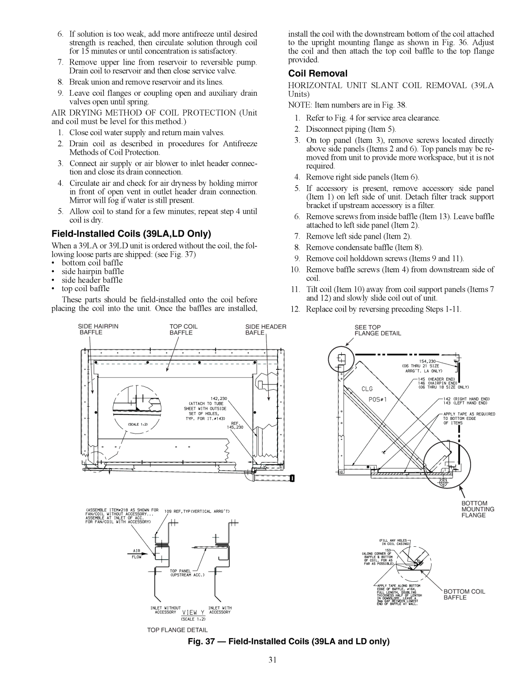
When a 39LA or 39LD unit is ordered without the coil, the fol- lowing loose parts are shipped: (see Fig. 37)

bottom coil baffle

side hairpin baffle

side header baffle

top coil baffle

These parts should be field-installed onto the coil before placing the coil into the unit. Once the baffles are installed,

install the coil with the downstream bottom of the coil attached to the upright mounting flange as shown in Fig. 36. Adjust the coil and then attach the top coil baffle to the top flange provided.

Coil Removal

HORIZONTAL UNIT SLANT COIL REMOVAL (39LA Units)

NOTE: Item numbers are in Fig. 38.

1.Refer to Fig. 4 for service area clearance.

2.Disconnect piping (Item 5).

3.On top panel (Item 3), remove screws located directly above side panels (Items 2 and 6). Top panels may be re- moved from unit to provide more workspace, but it is not required.

4.Remove right side panels (Item 6).

5.If accessory is present, remove accessory side panel (Item 1) on left side of unit. Detach filter track support bracket if upstream accessory is a filter.

6.Remove screws from inside baffle (Item 13). Leave baffle attached to left side panel (Item 2).

7.Remove left side panel (Item 2).

8.Remove condensate baffle (Item 8).

9.Remove coil holddown screws (Items 9 and 11).

10.Remove baffle screws (Item 4) from downstream side of coil.

11.Tilt coil (Item 10) away from coil support panels (Items 7 and 12) and slowly slide coil out of unit.

12.Replace coil by reversing preceding Steps 1-11.

SIDE HAIRPIN

TOP COIL

SIDE HEADER

SEE TOP

BAFFLE

BAFFLE

BAFLE

FLANGE DETAIL

BOTTOM

MOUNTING

FLANGE

BOTTOM COIL

BAFFLE

TOP FLANGE DETAIL

Fig. 37 — Field-Installed Coils (39LA and LD only)

31

Page 31
Image 31
Carrier 39LG, 39LB, 39LD, 39LC, 39LE, 39LF, 39LH03-25 specifications Field-Installed Coils 39LA,LD Only, Coil Removal

39LG, 39LH03-25, 39LD, 39LE, 39LB specifications

The Carrier 39 series, encompassing models 39LA, 39LF, 39LC, 39LB, and 39LE, represents a prominent line of rooftop packaged units that combine robust performance, energy efficiency, and advanced technology for commercial applications. Designed to provide reliable heating and cooling solutions, these units stand out for their versatility and innovative features.

The 39LA model offers high efficiency and flexibility, making it ideal for various building types. It incorporates advanced economizer capabilities that enhance indoor air quality while reducing energy costs. The unit is equipped with a dual-walled cabinet, which not only improves durability but also ensures quiet operation, making it suitable for noise-sensitive environments.

The 39LF model further enhances energy savings, featuring a unique hybrid heat pump system. This system allows for both heating and cooling through an integrated design, reducing the need for separate systems and streamlining maintenance requirements. The 39LF also boasts high Seasonal Energy Efficiency Ratio (SEER) ratings, contributing to lower operating costs without compromising comfort.

The 39LC variant excels in humid climates, employing advanced dehumidification technologies that effectively manage indoor moisture levels. This model is often utilized in environments such as gyms, restaurants, and hotels where humidity control is vital. Its variable-speed compressors adjust output based on demand, optimizing energy consumption while maintaining consistent comfort levels.

The 39LB model focuses on enhanced filtration and air quality improvements. Its engineered design accommodates high-efficiency particulate air (HEPA) filters, crucial for spaces that require stringent air quality standards. This model also includes smart controls that allow for precise temperature adjustments, ensuring optimal comfort in any setting.

Finally, the 39LE unit emphasizes user-friendly interfaces and smart technology integration. The built-in Wi-Fi capability enables remote monitoring and operation, allowing managers to adjust settings from anywhere, improving overall energy management. Additionally, the 39LE’s compatibility with Building Management Systems (BMS) facilitates seamless integration into existing setups.

In summary, the Carrier 39 series 39LA, 39LF, 39LC, 39LB, and 39LE present a comprehensive array of features designed for various commercial heating and cooling applications. With an emphasis on energy efficiency, advanced air quality management, and user-friendly technology, these units continue to set the standard for rooftop packaged units in the industry. Their innovative characteristics not only enhance comfort but also promote sustainability, making them a smart choice for modern commercial environments.