Carrier 39LG, 39LB, 39LD, 39LA, 39LC, 39LE, 39LF, 39LH03-25 specifications = 1.68 x .33 x

Models: 39LG 39LH03-25 39LD 39LE 39LB 39LC 39LF 39LA

1 40
Download 40 pages 63.94 Kb
Page 23
Image 23

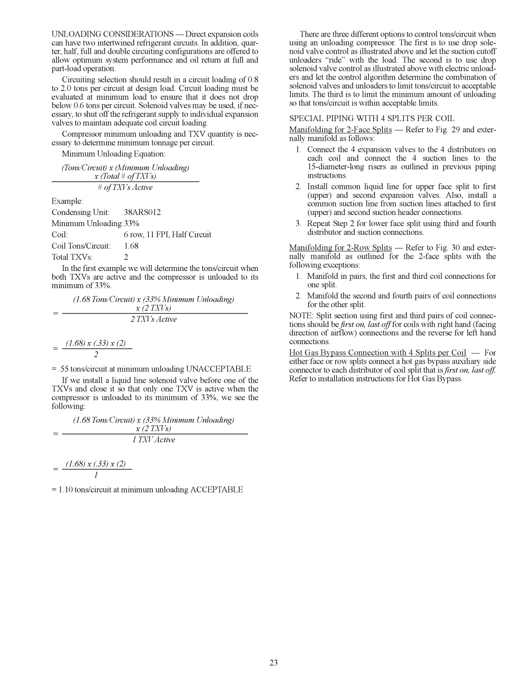
UNLOADING CONSIDERATIONS — Direct expansion coils can have two intertwined refrigerant circuits. In addition, quar- ter, half, full and double circuiting configurations are offered to allow optimum system performance and oil return at full and part-load operation.

Circuiting selection should result in a circuit loading of 0.8 to 2.0 tons per circuit at design load. Circuit loading must be evaluated at minimum load to ensure that it does not drop below 0.6 tons per circuit. Solenoid valves may be used, if nec- essary, to shut off the refrigerant supply to individual expansion valves to maintain adequate coil circuit loading.

Compressor minimum unloading and TXV quantity is nec- essary to determine minimum tonnage per circuit.

Minimum Unloading Equation:

(Tons/Circuit) x (Minimum Unloading)

x (Total # of TXVs)

# of TXVs Active

Example:

Condensing Unit: 38ARS012

Minimum Unloading:33%

Coil:

6 row, 11 FPI, Half Circuit

Coil Tons/Circuit:

1.68

Total TXVs:

2

In the first example we will determine the tons/circuit when both TXVs are active and the compressor is unloaded to its minimum of 33%.


(1.68 Tons/Circuit) x (33% Minimum Unloading)

=

x (2 TXVs)

2 TXVs Active


=(1.68) x (.33) x (2)

2

=.55 tons/circuit at minimum unloading UNACCEPTABLE

If we install a liquid line solenoid valve before one of the TXVs and close it so that only one TXV is active when the compressor is unloaded to its minimum of 33%, we see the following:


(1.68 Tons/Circuit) x (33% Minimum Unloading)

=

x (2 TXVs)

1 TXV Active


=(1.68) x (.33) x (2)

1

=1.10 tons/circuit at minimum unloading ACCEPTABLE

There are three different options to control tons/circuit when using an unloading compressor. The first is to use drop sole- noid valve control as illustrated above and let the suction cutoff unloaders “ride” with the load. The second is to use drop solenoid valve control as illustrated above with electric unload- ers and let the control algorithm determine the combination of solenoid valves and unloaders to limit tons/circuit to acceptable limits. The third is to limit the minimum amount of unloading so that tons/circuit is within acceptable limits.

SPECIAL PIPING WITH 4 SPLITS PER COIL

Manifolding for 2-Face Splits — Refer to Fig. 29 and exter- nally manifold as follows:

1.Connect the 4 expansion valves to the 4 distributors on each coil and connect the 4 suction lines to the 15-diameter-long risers as outlined in previous piping instructions.

2.Install common liquid line for upper face split to first (upper) and second expansion valves. Also, install a common suction line from suction lines attached to first (upper) and second suction header connections.

3.Repeat Step 2 for lower face split using third and fourth distributor and suction connections.

Manifolding for 2-Row Splits — Refer to Fig. 30 and exter- nally manifold as outlined for the 2-face splits with the following exceptions:

1.Manifold in pairs, the first and third coil connections for one split.

2.Manifold the second and fourth pairs of coil connections for the other split.

NOTE: Split section using first and third pairs of coil connec- tions should be first on, last off for coils with right hand (facing direction of airflow) connections and the reverse for left hand connections.

Hot Gas Bypass Connection with 4 Splits per Coil — For either face or row splits connect a hot gas bypass auxiliary side connector to each distributor of coil split that is first on, last off. Refer to installation instructions for Hot Gas Bypass.

23

Page 23
Image 23
Carrier 39LG, 39LB, 39LD, 39LA, 39LC, 39LE, 39LF, 39LH03-25 specifications = 1.68 x .33 x

39LG, 39LH03-25, 39LD, 39LE, 39LB specifications

The Carrier 39 series, encompassing models 39LA, 39LF, 39LC, 39LB, and 39LE, represents a prominent line of rooftop packaged units that combine robust performance, energy efficiency, and advanced technology for commercial applications. Designed to provide reliable heating and cooling solutions, these units stand out for their versatility and innovative features.

The 39LA model offers high efficiency and flexibility, making it ideal for various building types. It incorporates advanced economizer capabilities that enhance indoor air quality while reducing energy costs. The unit is equipped with a dual-walled cabinet, which not only improves durability but also ensures quiet operation, making it suitable for noise-sensitive environments.

The 39LF model further enhances energy savings, featuring a unique hybrid heat pump system. This system allows for both heating and cooling through an integrated design, reducing the need for separate systems and streamlining maintenance requirements. The 39LF also boasts high Seasonal Energy Efficiency Ratio (SEER) ratings, contributing to lower operating costs without compromising comfort.

The 39LC variant excels in humid climates, employing advanced dehumidification technologies that effectively manage indoor moisture levels. This model is often utilized in environments such as gyms, restaurants, and hotels where humidity control is vital. Its variable-speed compressors adjust output based on demand, optimizing energy consumption while maintaining consistent comfort levels.

The 39LB model focuses on enhanced filtration and air quality improvements. Its engineered design accommodates high-efficiency particulate air (HEPA) filters, crucial for spaces that require stringent air quality standards. This model also includes smart controls that allow for precise temperature adjustments, ensuring optimal comfort in any setting.

Finally, the 39LE unit emphasizes user-friendly interfaces and smart technology integration. The built-in Wi-Fi capability enables remote monitoring and operation, allowing managers to adjust settings from anywhere, improving overall energy management. Additionally, the 39LE’s compatibility with Building Management Systems (BMS) facilitates seamless integration into existing setups.

In summary, the Carrier 39 series 39LA, 39LF, 39LC, 39LB, and 39LE present a comprehensive array of features designed for various commercial heating and cooling applications. With an emphasis on energy efficiency, advanced air quality management, and user-friendly technology, these units continue to set the standard for rooftop packaged units in the industry. Their innovative characteristics not only enhance comfort but also promote sustainability, making them a smart choice for modern commercial environments.