!WARNING

ELECTRICAL SHOCK HAZARD

Failure to follow this warning could result in personal injury or death.

Before performing service or maintenance, be sure indoor unit main power switch is turned OFF and indoor blower has stopped.

Lock out and tag switch with suitable warning label.

Power Wiring

1.Mount outdoor power disconnect. The unit is factory wired for the voltage shown on the unit nameplate. The fused dis- connect switch must be provided within sight of the unit, readily accessible, but out of reach of children. Provisions for locking the disconnect switch on the OFF (open) posi- tion is advisable. The disconnect switch must comply with NEC and local codes. Protect the unit and wiring using only the recommended fuse/circuit breaker size. See Table 10..

2.Run power wiring from main box to disconnect per NEC and local codes.

3.Run power wiring from the disconnect switch to outdoor unit. Use only minimum 60_C copper conductors between the disconnect switch and the unit for field power connec- tion.

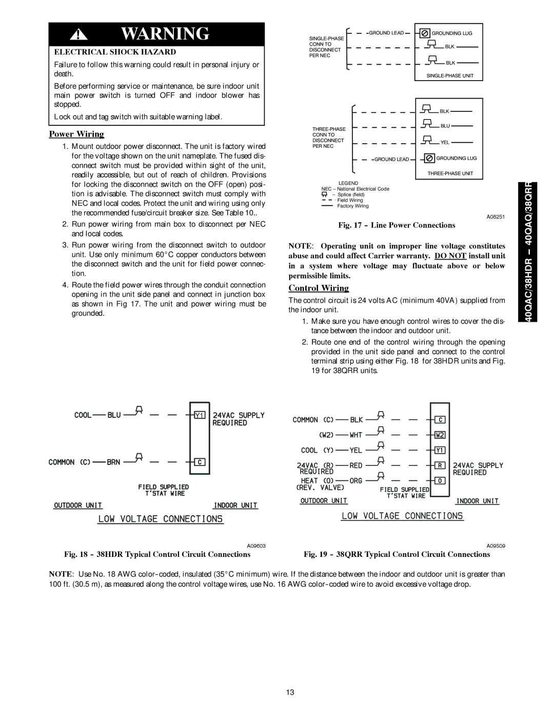
4.Route the field power wires through the conduit connection opening in the unit side panel and connect in junction box as shown in Fig 17. The unit and power wiring must be grounded.

GROUND LEAD

GROUNDING LUG

SINGLE-PHASE


CONN TO

BLK

DISCONNECT


PER NEC


BLK


SINGLE-PHASE UNIT


BLK

THREE-PHASE

BLU


CONN TO


DISCONNECT

YEL

PER NEC


GROUND LEAD

GROUNDING LUG


THREE-PHASE UNIT

LEGEND


NEC -- National Electrical Code


-- Splice (field)


Field Wiring


Factory Wiring


A08251

Fig. 17 - Line Power Connections

NOTE: Operating unit on improper line voltage constitutes abuse and could affect Carrier warranty. DO NOT install unit in a system where voltage may fluctuate above or below permissible limits.

Control Wiring

The control circuit is 24 volts AC (minimum 40VA) supplied from the indoor unit.

1.Make sure you have enough control wires to cover the dis- tance between the indoor and outdoor unit.

2.Route one end of the control wiring through the opening provided in the unit side panel and connect to the control terminal strip using either Fig. 18 for 38HDR units and Fig. 19 for 38QRR units.

40QAC/38HDR -- 40QAQ/38QRR

Y1

A09603

A09509

Fig. 18 - 38HDR Typical Control Circuit Connections

Fig. 19 - 38QRR Typical Control Circuit Connections

NOTE: Use No. 18 AWG color-coded, insulated (35_C minimum) wire. If the distance between the indoor and outdoor unit is greater than 100 ft. (30.5 m), as measured along the control voltage wires, use No. 16 AWG color-coded wire to avoid excessive voltage drop.

13

Page 13
Image 13
Carrier 40QAC installation instructions Power Wiring, Line Power Connections

40QAC specifications

The Carrier 40QAC is a standout product in the realm of commercial air conditioning systems. This air-cooled chiller is designed to meet a variety of cooling needs while ensuring energy efficiency and reliability. One of the most notable features of the 40QAC is its advanced scroll compressor technology, which is engineered to provide consistent performance with reduced noise levels. This makes it an ideal choice for applications where minimizing sound pollution is crucial, such as in urban settings or near sensitive environments.

In terms of energy efficiency, the 40QAC boasts impressive ratings, with a high coefficient of performance (COP) that helps to lower operational costs and reduce environmental impact. Its design integrates various energy-saving features, including variable speed fans and a robust control system that optimizes performance based on real-time demand. This adaptability allows the chiller to maintain comfort levels while consuming less energy than traditional models.

The 40QAC is equipped with a microprocessor-based control system that simplifies operation and enhances user experience. This intelligent control interface allows operators to monitor performance metrics, adjust settings, and troubleshoot any issues remotely, increasing overall system reliability. The system is also designed to be compatible with building management systems, which facilitates seamless integration into existing infrastructure.

Another prominent characteristic of the Carrier 40QAC is its robust construction. Built with high-quality materials, it offers excellent durability and longevity, even in challenging environmental conditions. The unit also incorporates features to streamline maintenance, such as accessible component layout and easy-to-remove panels, ensuring that downtime for servicing is minimized.

Safety is another critical aspect of the Carrier 40QAC’s design. It’s engineered with numerous safety protocols to protect against overheating, overpressure, and other potential hazards, guaranteeing both system integrity and peace of mind for operators.

Overall, the Carrier 40QAC is a versatile and efficient solution for commercial cooling needs. With its technological advancements, energy-saving features, and robust design, it stands out as a reliable choice for businesses looking to balance performance with sustainability. The 40QAC not only promises efficient cooling but does so while aligning with the growing demand for eco-friendly solutions in today's marketplace.