Section 7: Replacement Procedures
7Disconnect the sensor switch wiring harness from the main circuit board and withdraw switch (1) from printer.
8Feed the wiring harness of replacement switch (1) through the slot adjacent to the motor.
9Apply switch (1) against the printer frame and secure using two screws (8).
NOTE: A properly oriented sensor switch will permit its mounting orifices to align with those of the frame while its contact arm protrudes through the paper ramp.
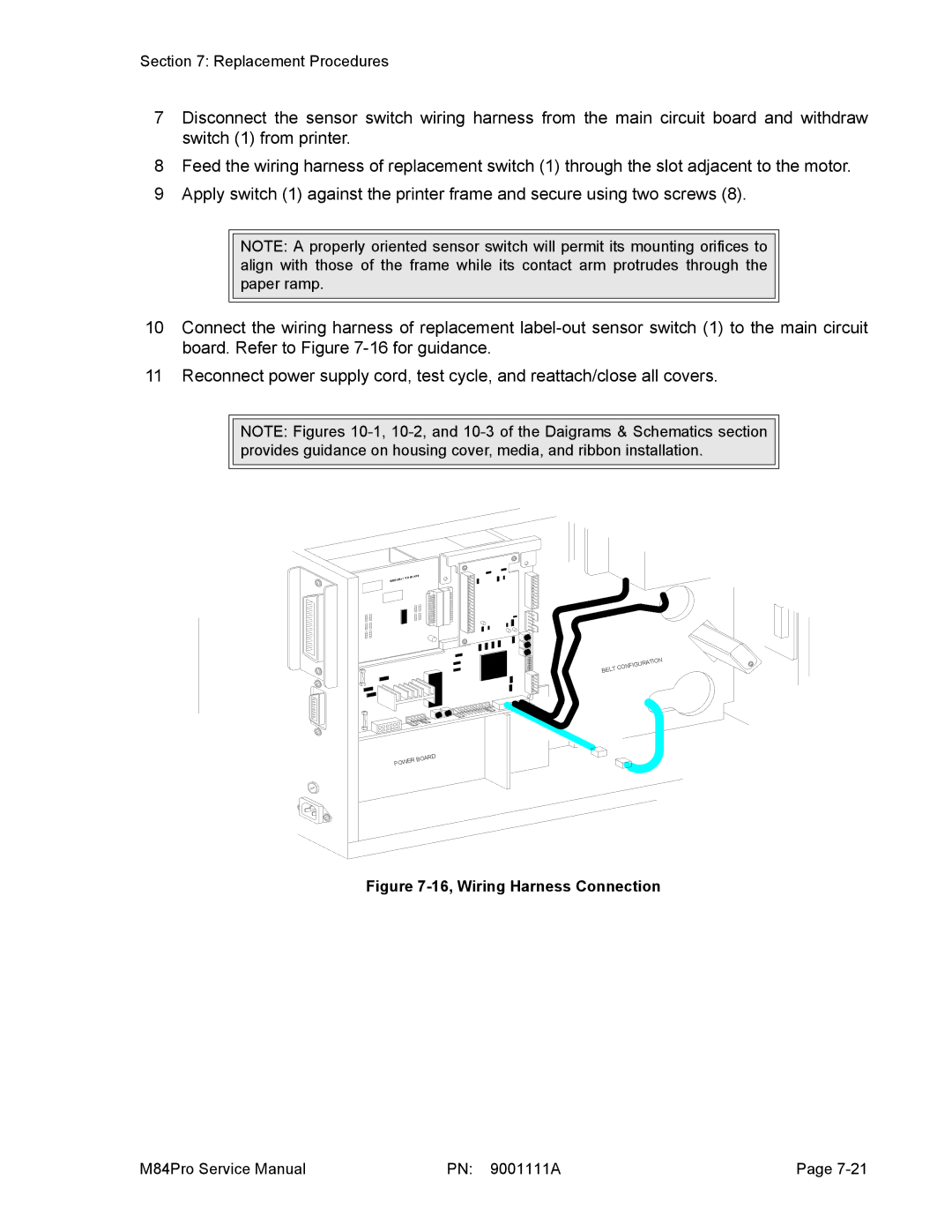
10Connect the wiring harness of replacement
11Reconnect power supply cord, test cycle, and reattach/close all covers.
NOTE: Figures
84+RS | BOARD |
IEEE12 |
|
|
|
| N |
|
| ATIO | |
| IGUR |
| |
BELT | CONF |
|
|
|
|
| |
POWER BOARD
Figure 7-16, Wiring Harness Connection
M84Pro Service Manual | PN: 9001111A | Page |