Section 7: Replacement Procedures
2
3 ![]()
4 ![]() 9
9 ![]()
|
| HTER | |
| E | DAUG | D |
| BOAR | ||
RFAC |
|
| |
INTE | D |
|
|
BOAR |
|
| |
|
| D |
|
|
| UITBOAR |
|
| MAIN | CIRC |
|
|
|
| 1 |
|
| D |
|
| ERBOAR |
| |
| POW |
| 7 |
|
|
| |
9 | 6 | |
8 | ||
| ||
| 5 |
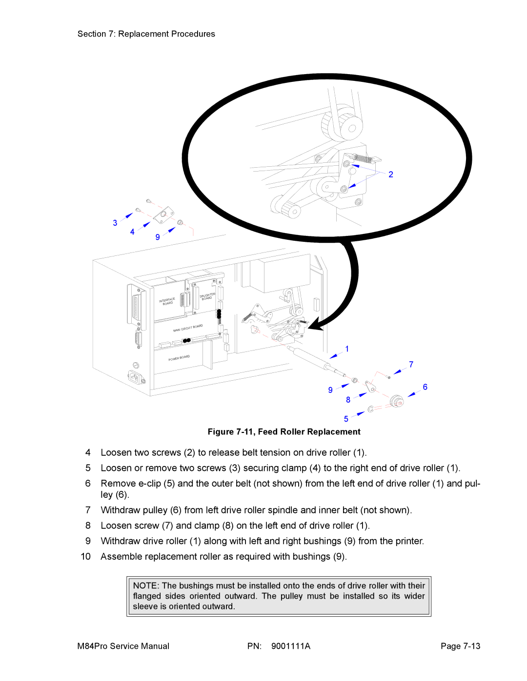
Figure 7-11, Feed Roller Replacement
4Loosen two screws (2) to release belt tension on drive roller (1).
5Loosen or remove two screws (3) securing clamp (4) to the right end of drive roller (1).
6Remove
7Withdraw pulley (6) from left drive roller spindle and inner belt (not shown).
8Loosen screw (7) and clamp (8) on the left end of drive roller (1).
9Withdraw drive roller (1) along with left and right bushings (9) from the printer.
10Assemble replacement roller as required with bushings (9).
NOTE: The bushings must be installed onto the ends of drive roller with their flanged sides oriented outward. The pulley must be installed so its wider sleeve is oriented outward.
M84Pro Service Manual | PN: 9001111A | Page |