Section 10: Diagrams & Schematics
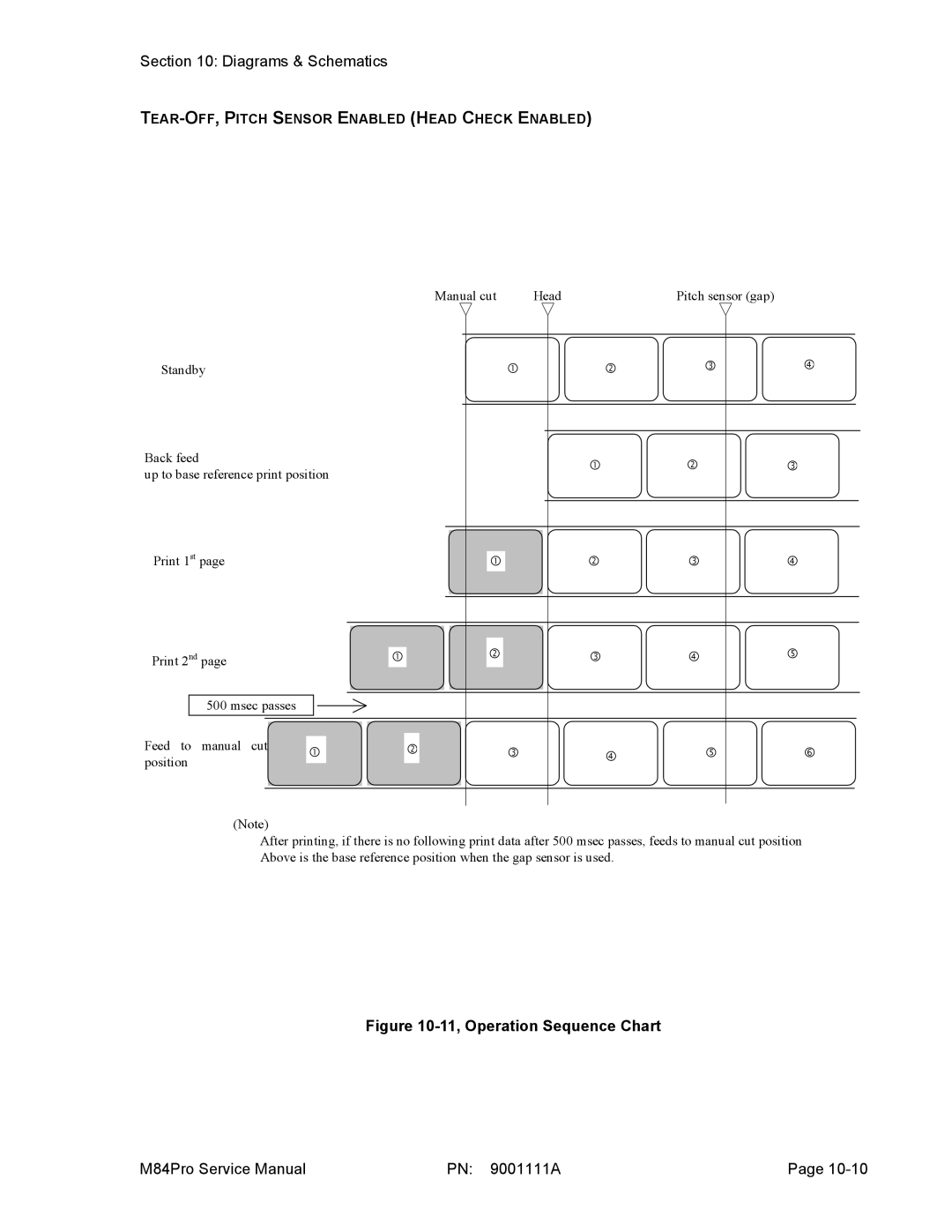
TEAR-OFF, PITCH SENSOR ENABLED (HEAD CHECK ENABLED)
Manual cut |
| Head | Pitch sensor (gap) |
|
Standby | c | d | e | f |
Back feed |
| c |
|
|
| d |
|
|
| e |
|
up to base reference print position |
|
|
|
|
|
|
|
| |||
|
|
|
|
|
|
|
|
|
|
| |
|
|
|
|
|
|
|
|
|
|
|
|
Print 1st page |
|
|
|
|
|
|
|
|
|
| c |
|
| d |
| e |
| f | |
|
|
|
|
|
|
|
|
|
|
|
|
|
|
|
|
|
|
|
|
|
|
|
|
|
|
|
|
| d |
|
|
|
|
|
| g | |
Print 2nd page |
| c |
|
|
| e |
| f | |||||
|
|
|
|
|
|
|
|
|
|
|
|
|
|
500 msec passes
Feed to | manual | cut | c | d | e | f | g | h |
position |
|
| ||||||
|
|
|
|
|
|
|
|
(Note)
After printing, if there is no following print data after 500 msec passes, feeds to manual cut position Above is the base reference position when the gap sensor is used.
Figure 10-11, Operation Sequence Chart
M84Pro Service Manual | PN: 9001111A | Page |