Section 4: Accessories Installation
3
4
1
2
5
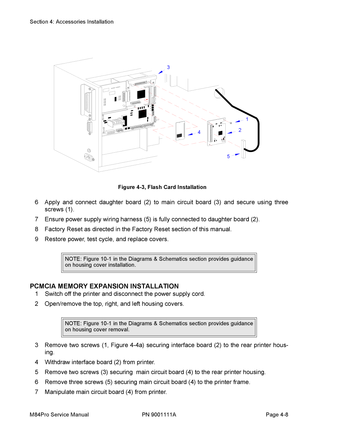
Figure 4-3, Flash Card Installation
6Apply and connect daughter board (2) to main circuit board (3) and secure using three screws (1).
7Ensure power supply wiring harness (5) is fully connected to daughter board (2).
8Factory Reset as directed in the Factory Reset section of this manual.
9Restore power, test cycle, and replace covers.
NOTE: Figure
PCMCIA MEMORY EXPANSION INSTALLATION
1Switch off the printer and disconnect the power supply cord.
2Open/remove the top, right, and left housing covers.
NOTE: Figure
3Remove two screws (1, Figure
4Withdraw interface board (2) from printer.
5Remove two screws (3) securing main circuit board (4) to the rear printer housing.
6Remove three screws (5) securing main circuit board (4) to the printer frame.
7Manipulate main circuit board (4) from printer.
M84Pro Service Manual | PN 9001111A | Page |