Section 4: Accessories Installation
NOTE: Figures
12 Restore power and test cycle.
|
|
|
|
|
|
|
|
|
|
|
|
|
| L |
|
|
|
|
|
|
|
|
|
|
|
|
|
|
|
| C |
|
|
|
|
|
|
|
|
|
|
|
|
|
|
|
| D |
| |
|
|
|
|
|
|
|
|
|
|
|
|
|
| P |
|
|
|
|
|
|
|
|
|
|
|
|
|
|
|
| A |
|
|
|
|
|
|
|
|
|
|
|
|
|
|
|
| N |
|
|
|
|
|
|
|
|
|
|
|
|
|
|
|
| EL B |
|
|
|
|
|
|
|
|
|
|
| TER |
|
|
|
| O | A | R |
|
|
|
|
|
|
|
| GH |
|
|
|
|
|
| ||
|
|
| CE |
|
|
|
| DAU | D |
|
|
|
|
|
| D |
|
|
|
|
|
|
| AR |
|
|
|
|
|
|
| ||
RFA |
|
|
|
| BO |
|
|
|
|
|
|
|
| |||
INTE |
|
| D |
|
|
|
|
|
|
|
|
|
|
|
|
|
| AR |
|
|
|
|
|
|
|
|
|
|
|
|
| ||
BO |
|
|
|
|
|
|
|
|
|
|
|
|
|
|
| |
|
|
|
|
|
|
|
|
|
|
|
|
|
| N |
|
|
|
|
|
|
|
|
|
|
|
|
|
|
| ATIO |
|
| |
|
|
|
|
|
|
|
|
|
|
|
| UR |
|
|
| |
|
|
|
|
|
|
|
|
|
|
| FIG |
|
|
|
| |
|
|
|
|
|
|
|
|
|
|
| ON |
|
|
|
|
|
|
|
|
|
|
|
|
|
|
| T C |
|
|
|
|
|
|
|
|
|
|
|
|
|
|
|
| BEL |
|
|
|
|
|
|
|
|
|
|
|
|
|
| 5 |
|
|
|
|
|
|
|
|
|
|
|
|
|
|
| D |
|
|
|
|
|
|
|
|
|
|
|
|
|
|
| AR |
|
|
|
|
|
|
|
|
| |
|
|
|
|
| UIT BO |
|
|
|
|
|
|
|
|
|
| |
|
|
| IRC |
|
|
|
|
|
|
|
|
|
|
| ||
|
| N C |
|
|
|
|
|
|
|
|
|
|
|
|
| |
MAI |
|
|
|
|
|
|
|
|
|
|
|
|
|
| ||
|
|
|
|
|
|
|
|
|
|
| 3 |
|
|
|
|
|
|
|
|
|
| D |
|
|
|
|
|
|
|
|
|
|
|
|
|
|
| AR |
|
|
|
|
|
|
|
|
|
|
| |
WERBO |
|
|
|
|
|
|
|
|
|
|
|
| ||||
PO |
|
|
|
|
|
|
|
|
|
|
|
|
|
|
|
|
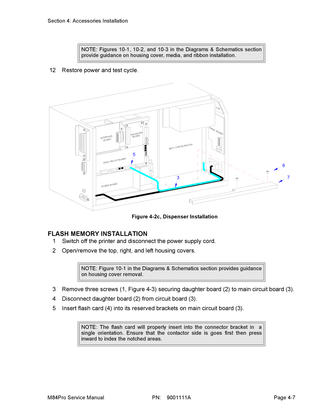
Figure 4-2c, Dispenser Installation
FLASH MEMORY INSTALLATION
6
7
1Switch off the printer and disconnect the power supply cord.
2Open/remove the top, right, and left housing covers.
NOTE: Figure
3Remove three screws (1, Figure
4Disconnect daughter board (2) from circuit board (3).
5Insert flash card (4) into its reserved brackets on main circuit board (3).
NOTE: The flash card will properly insert into the connector bracket in a single orientation. Ensure that the contactor side is goes first then press inward to index the notched areas.
M84Pro Service Manual | PN: 9001111A | Page |