Section 4: Accessories Installation
4
1
3
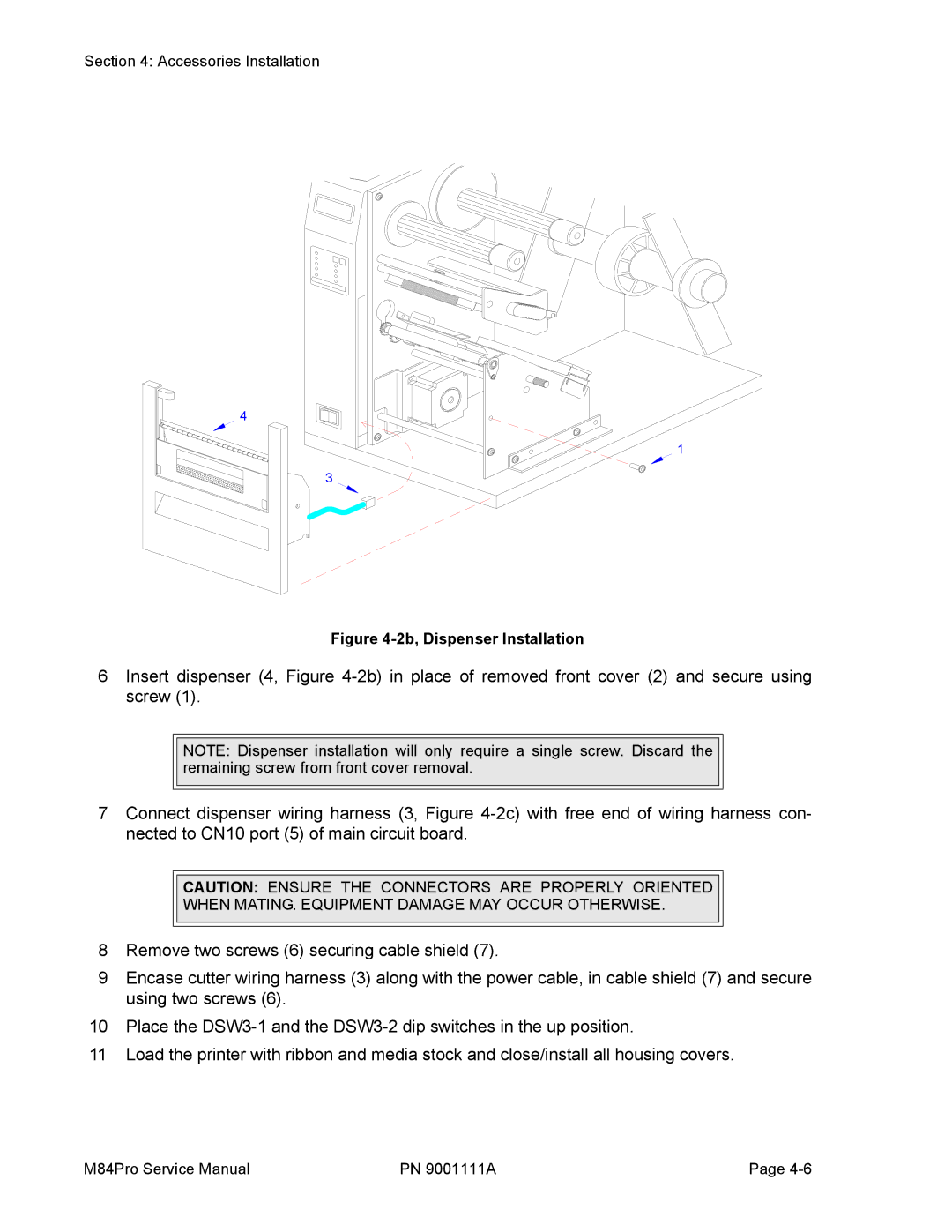
Figure 4-2b, Dispenser Installation
6Insert dispenser (4, Figure
NOTE: Dispenser installation will only require a single screw. Discard the remaining screw from front cover removal.
7Connect dispenser wiring harness (3, Figure
CAUTION: ENSURE THE CONNECTORS ARE PROPERLY ORIENTED
WHEN MATING. EQUIPMENT DAMAGE MAY OCCUR OTHERWISE.
8Remove two screws (6) securing cable shield (7).
9Encase cutter wiring harness (3) along with the power cable, in cable shield (7) and secure using two screws (6).
10Place the
11 Load the printer with ribbon and media stock and close/install all housing covers.
M84Pro Service Manual | PN 9001111A | Page |
