REPLACEMENT PROCEDURES | 7 |
The M84PRO Printer contains replaceable components and
MAIN CIRCUIT BOARD REPLACEMENT
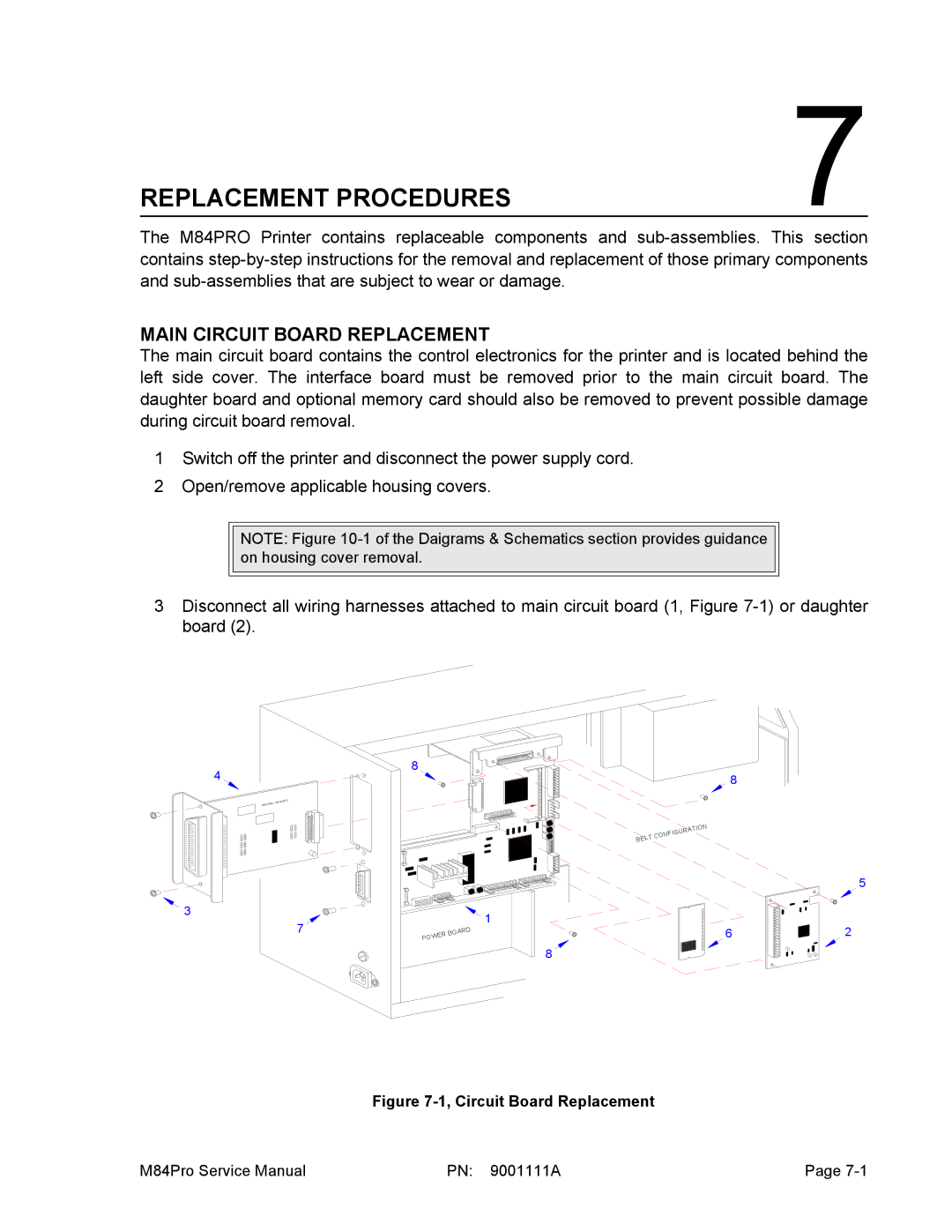
The main circuit board contains the control electronics for the printer and is located behind the left side cover. The interface board must be removed prior to the main circuit board. The daughter board and optional memory card should also be removed to prevent possible damage during circuit board removal.
1Switch off the printer and disconnect the power supply cord.
2Open/remove applicable housing covers.
NOTE: Figure
3Disconnect all wiring harnesses attached to main circuit board (1, Figure
4
| RD |
IEEE1284 | + RSBOA |
3
7
8
1
|
|
| D |
|
| AR | |
| R BO |
| |
WE |
|
| |
PO |
|
|
|
8
8
|
|
|
|
| N |
|
|
|
| TIO | |
|
|
| RA |
| |
|
| GU |
|
| |
| NFI |
|
|
| |
LTCO |
|
|
|
| |
BE |
|
|
|
|
|
6
5
2
Figure 7-1, Circuit Board Replacement
M84Pro Service Manual | PN: 9001111A | Page |