Section 7: Replacement Procedures
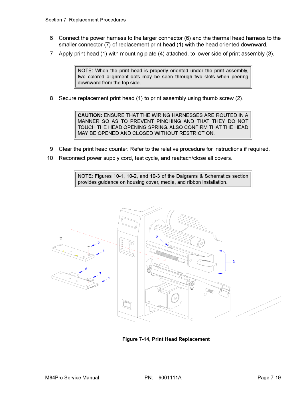
6Connect the power harness to the larger connector (6) and the thermal head harness to the smaller connector (7) of replacement print head (1) with the head oriented downward.
7Apply print head (1) with mounting plate (4) attached, to lower side of print assembly (3).
NOTE: When the print head is properly oriented under the print assembly, two colored alignment dots may be seen through two slots when peering downward from the top side.
8 Secure replacement print head (1) to print assembly using thumb screw (2).
CAUTION: ENSURE THAT THE WIRING HARNESSES ARE ROUTED IN A
MANNER SO AS TO PREVENT PINCHING AND THAT THEY DO NOT
TOUCH THE HEAD OPENING SPRING. ALSO CONFIRM THAT THE HEAD
MAY BE OPENED AND CLOSED WITHOUT RESTRICTION.
9Clear the print head counter. Refer to the relative procedure for instructions if required.
10Reconnect power supply cord, test cycle, and reattach/close all covers.
NOTE: Figures
2
5
![]() 4
4
3
6
7 1
Figure 7-14, Print Head Replacement
M84Pro Service Manual | PN: 9001111A | Page |