Section 6: Troubleshooting
NOTE: Voltage readings must be +/- 10% of specification for proper operation.
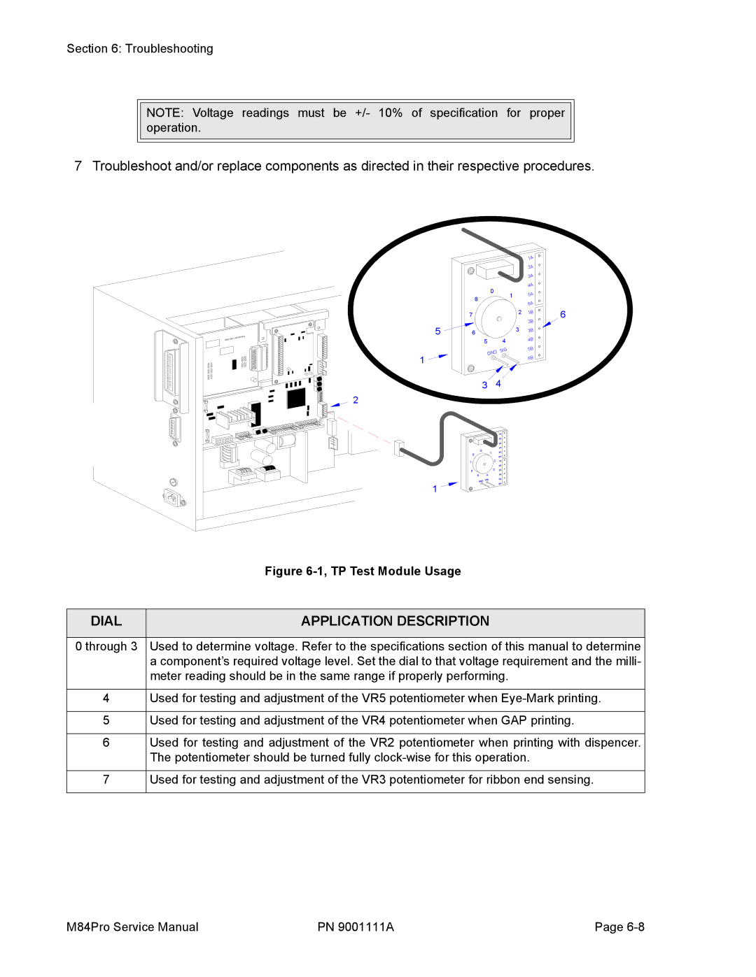
7 Troubleshoot and/or replace components as directed in their respective procedures.
| RD |
IEEE1284 | + RS BOA |
|
|
|
|
|
|
| 1A |
|
|
|
|
|
|
| 2A |
|
|
|
|
|
|
| 3A |
|
|
|
|
| 0 |
| 4A |
|
|
|
|
| 1 | 5A |
| |
| 8 |
|
|
|
| ||
|
|
|
|
|
| ||
|
|
|
|
| 6A |
| |
|
|
|
|
|
|
| |
| 7 |
|
|
| 2 | 1B | 6 |
|
|
|
|
| 2B | ||
5 | 6 |
|
|
|
|
| |
|
|
| 3 | 3B |
| ||
|
|
|
|
|
| ||
|
|
|
| 5 | 4 | 4B |
|
|
|
|
|
|
| ||
|
|
|
| D SIG | 5B |
| |
1 |
|
|
| GN |
| 6B |
|
|
|
|
|
|
| ||
|
|
| 3 | 4 |
|
| |
2 |
|
|
|
|
|
|
|
|
|
|
|
| 1A |
|
|
|
|
|
|
| 2A |
|
|
|
|
|
|
| 3A |
|
|
|
| 0 |
|
| 4A |
|
|
| 8 |
| 1 | 5A |
|
| |
|
|
|
| 6A |
|
| |
|
|
|
|
|
|
| |
| 7 |
|
| 2 | 1B |
|
|
|
|
|
|
|
|
| |
|
|
|
|
| 2B |
|
|
| 6 |
|
| 3 | 3B |
|
|
| 5 |
|
| 4 | 4B |
|
|
| GND | SIG | 5B |
|
| ||
1 |
| 6B |
|
| |||
|
|
|
|
|
| ||
|
|
|
|
|
|
| |
| Figure |
|
|
DIAL | APPLICATION DESCRIPTION |
| |
0 through 3 Used to determine voltage. Refer to the specifications section of this manual to determine | |
| a component’s required voltage level. Set the dial to that voltage requirement and the milli- |
| meter reading should be in the same range if properly performing. |
4Used for testing and adjustment of the VR5 potentiometer when
5Used for testing and adjustment of the VR4 potentiometer when GAP printing.
6Used for testing and adjustment of the VR2 potentiometer when printing with dispencer. The potentiometer should be turned fully
7Used for testing and adjustment of the VR3 potentiometer for ribbon end sensing.
M84Pro Service Manual | PN 9001111A | Page |
