Section 7: Replacement Procedures
A
|
|
|
|
|
|
|
|
|
|
| ER |
|
|
|
|
|
|
|
|
|
|
|
|
|
|
| HT |
|
|
|
|
| |
|
|
|
|
|
|
|
| UG | D |
|
|
|
|
| ||
|
| E |
|
|
|
|
| DA |
|
|
|
|
|
|
| |
|
|
|
|
|
|
|
| AR |
|
|
|
|
| |||
| FAC |
|
|
|
|
| BO |
|
|
|
|
|
|
| ||
ER |
|
|
|
|
|
|
|
|
|
|
|
|
|
|
| |
INT |
| D |
|
|
|
|
|
|
|
|
|
|
|
|
|
|
| AR |
|
|
|
|
|
|
|
|
|
|
|
|
|
| |
BO |
|
|
|
|
|
|
|
|
|
|
|
|
|
|
|
|
|
|
|
|
|
|
|
|
|
|
|
|
|
|
|
| N |
|
|
|
|
|
|
|
|
|
|
|
|
|
|
| TIO | |
|
|
|
|
|
|
|
|
|
|
|
|
|
| RA |
| |
|
|
|
|
|
|
|
|
|
|
|
|
| IGU |
|
| |
|
|
|
|
|
|
|
|
|
|
|
| NF |
|
|
| |
|
|
|
|
|
|
|
| D |
|
| LTCO |
|
|
|
| |
|
|
|
|
|
|
|
|
|
| BE |
|
|
|
|
| |
|
|
|
|
|
|
| AR |
|
|
|
|
|
|
|
| |
|
|
|
|
|
| ITBO |
|
|
|
|
|
|
|
|
| |
|
|
|
|
| CU |
|
|
|
|
|
|
|
|
|
| |
|
|
| INCIR |
|
|
|
|
|
|
|
|
|
|
| ||
|
| MA |
|
|
|
|
|
|
|
|
|
|
|
|
| |
|
|
|
|
| RD |
|
|
|
|
|
|
|
|
|
| |
|
|
|
| OA |
|
|
|
|
|
|
|
|
|
|
| |
|
|
| R B |
|
|
|
|
|
|
|
|
|
|
|
| |
|
| WE |
|
|
|
|
|
|
|
|
|
|
|
|
| |
| PO |
|
|
|
|
|
|
|
|
|
|
|
|
|
| |
LCD
1
| P |
|
|
| A |
| |
|
| NE |
|
|
| L |
|
|
| B |
|
|
| O |
|
|
| A |
|
|
| R | D |
|
|
| |
|
|
| A |
B |
| B | |
|
| ||
C |
| C | 2 |
|
|
| |
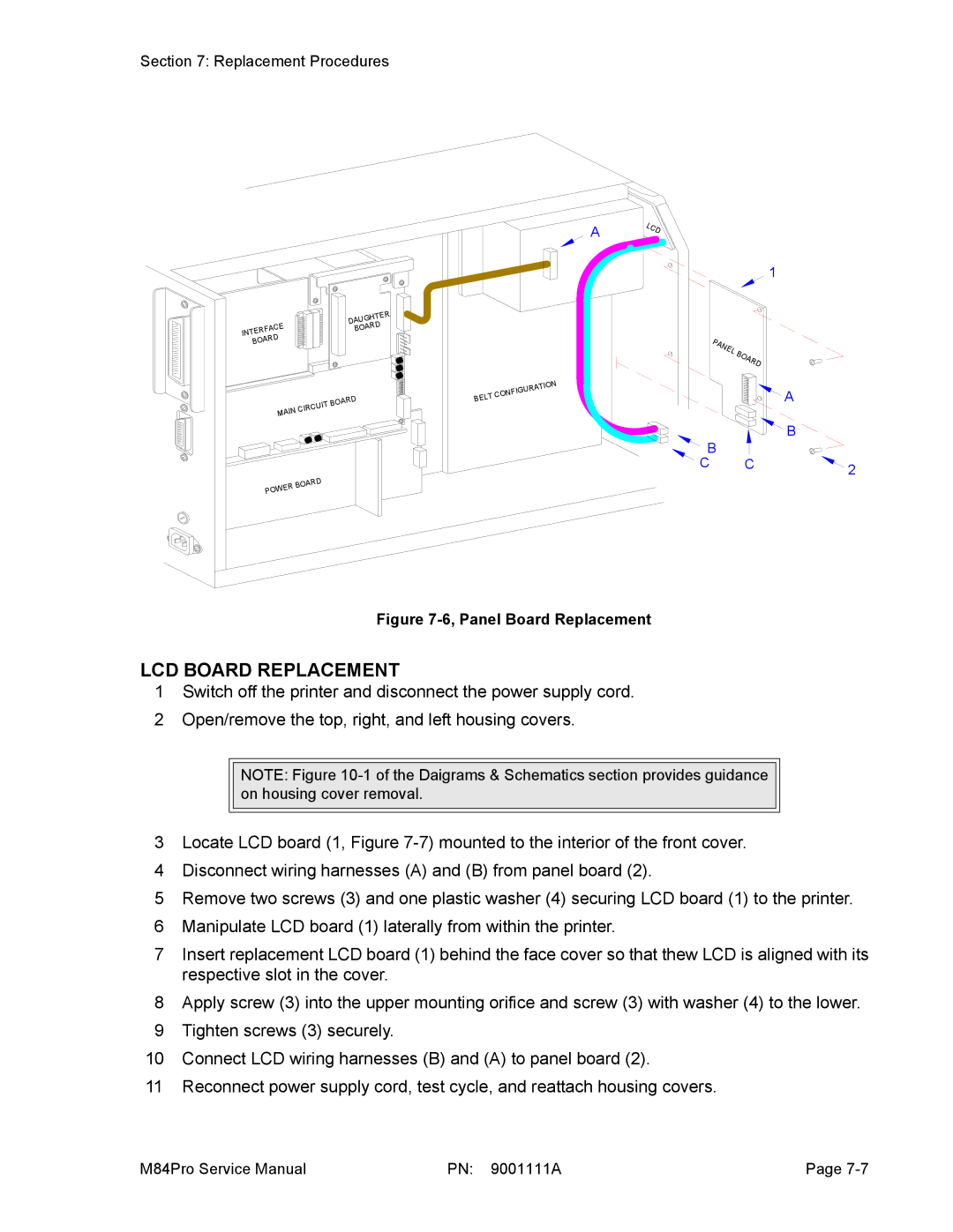
Figure 7-6, Panel Board Replacement
LCD BOARD REPLACEMENT
1Switch off the printer and disconnect the power supply cord.
2Open/remove the top, right, and left housing covers.
NOTE: Figure
3Locate LCD board (1, Figure
4Disconnect wiring harnesses (A) and (B) from panel board (2).
5Remove two screws (3) and one plastic washer (4) securing LCD board (1) to the printer.
6Manipulate LCD board (1) laterally from within the printer.
7Insert replacement LCD board (1) behind the face cover so that thew LCD is aligned with its respective slot in the cover.
8Apply screw (3) into the upper mounting orifice and screw (3) with washer (4) to the lower.
9Tighten screws (3) securely.
10Connect LCD wiring harnesses (B) and (A) to panel board (2).
11 Reconnect power supply cord, test cycle, and reattach housing covers.
M84Pro Service Manual | PN: 9001111A | Page |