Section 8: Adjustment Procedures
NOTE: Refer to TP Test Module Usage in the Troubleshooting section for additional instruction on test module use.
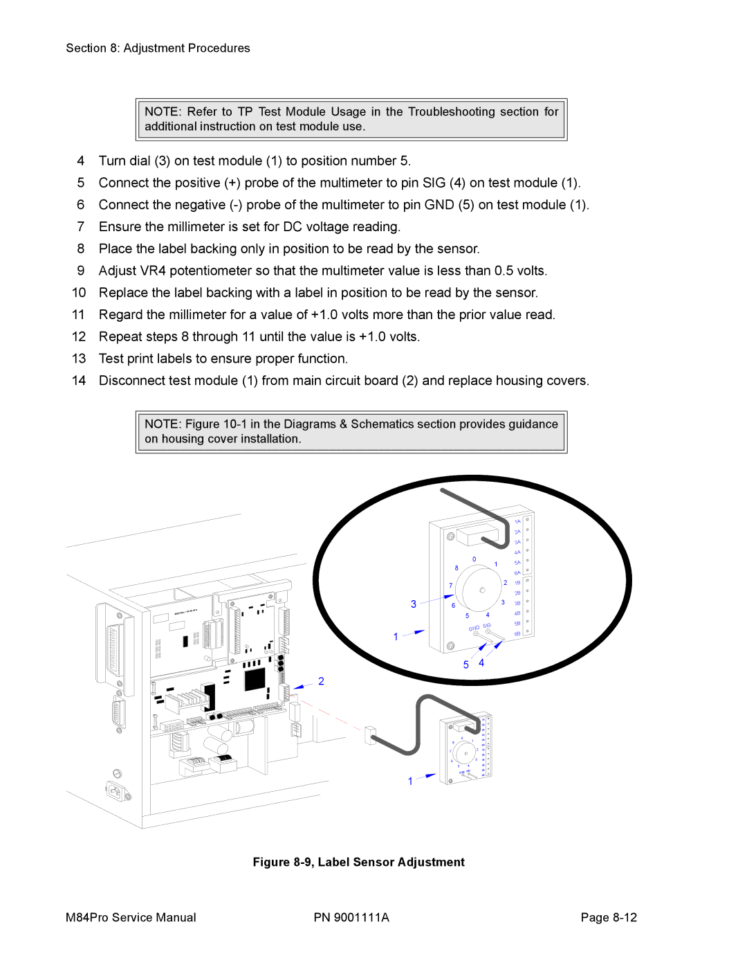
4Turn dial (3) on test module (1) to position number 5.
5Connect the positive (+) probe of the multimeter to pin SIG (4) on test module (1).
6Connect the negative
7Ensure the millimeter is set for DC voltage reading.
8Place the label backing only in position to be read by the sensor.
9Adjust VR4 potentiometer so that the multimeter value is less than 0.5 volts.
10Replace the label backing with a label in position to be read by the sensor.
11Regard the millimeter for a value of +1.0 volts more than the prior value read.
12Repeat steps 8 through 11 until the value is +1.0 volts.
13Test print labels to ensure proper function.
14Disconnect test module (1) from main circuit board (2) and replace housing covers.
NOTE: Figure
84 +RS | BOARD |
IEEE12 |
|
|
|
|
| 1A |
|
|
|
| 2A |
|
|
|
| 3A |
|
| 0 |
| 4A |
|
| 1 | 5A | |
| 8 |
| ||
|
|
| ||
|
|
| 6A | |
|
|
|
| |
| 7 |
| 2 | 1B |
|
|
|
| |
3 | 6 |
|
| 2B |
| 3 | 3B | ||
|
|
| ||
| 5 | 4 |
| 4B |
|
|
| ||
|
| D SIG |
| 5B |
|
|
|
| |
1 | GN |
| 6B | |
|
|
| ||
![]()
![]()
![]()
![]()
![]()
![]()
![]() 5 4 2
5 4 2![]()
![]()
![]()
![]()
![]()
![]()
![]()
![]()
![]()
![]()
![]()
![]()
![]()
![]()
![]()
![]()
![]()
![]()
![]()
![]()
![]()
![]()
![]()
![]()
![]()
![]()
![]()
![]()
![]()
|
| 1A |
|
| 2A |
|
| 3A |
0 |
| 4A |
1 | 5A | |
8 |
| |
| 6A | |
7 | 2 | 1B |
|
| |
|
| 2B |
6 | 3 | 3B |
5 | 4 | 4B |
| ||
GND | SIG | 5B |
1 |
| 6B |
|
|
Figure 8-9, Label Sensor Adjustment
M84Pro Service Manual | PN 9001111A | Page |