Section 7: Replacement Procedures
84 +RS | BOARD |
| |
IEEE12 |
|
BELT CO
NFIGURATION
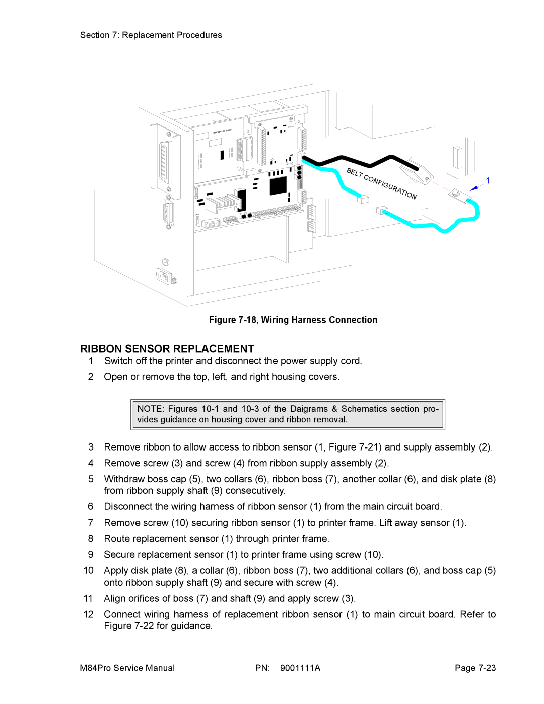
Figure 7-18, Wiring Harness Connection
RIBBON SENSOR REPLACEMENT
1
1Switch off the printer and disconnect the power supply cord.
2Open or remove the top, left, and right housing covers.
NOTE: Figures
3Remove ribbon to allow access to ribbon sensor (1, Figure
4Remove screw (3) and screw (4) from ribbon supply assembly (2).
5Withdraw boss cap (5), two collars (6), ribbon boss (7), another collar (6), and disk plate (8) from ribbon supply shaft (9) consecutively.
6Disconnect the wiring harness of ribbon sensor (1) from the main circuit board.
7Remove screw (10) securing ribbon sensor (1) to printer frame. Lift away sensor (1).
8Route replacement sensor (1) through printer frame.
9Secure replacement sensor (1) to printer frame using screw (10).
10Apply disk plate (8), a collar (6), ribbon boss (7), two additional collars (6), and boss cap (5) onto ribbon supply shaft (9) and secure with screw (4).
11Align orifices of boss (7) and shaft (9) and apply screw (3).
12Connect wiring harness of replacement ribbon sensor (1) to main circuit board. Refer to Figure
M84Pro Service Manual | PN: 9001111A | Page |