Section 8: Adjustment Procedures
5Place the strip between the upper and lower feed rollers on one end and latch media cover.
6Slowly pull the tension gauge sufficiently enough to take a reading.
7Repeat steps 5 and 6 for the opposite end of feed roller assemblies.
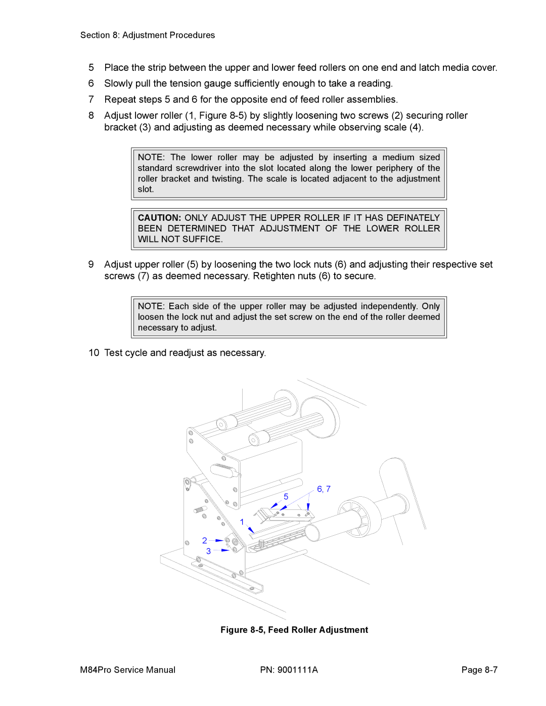
8Adjust lower roller (1, Figure
NOTE: The lower roller may be adjusted by inserting a medium sized standard screwdriver into the slot located along the lower periphery of the roller bracket and twisting. The scale is located adjacent to the adjustment slot.
CAUTION: ONLY ADJUST THE UPPER ROLLER IF IT HAS DEFINATELY
BEEN DETERMINED THAT ADJUSTMENT OF THE LOWER ROLLER
WILL NOT SUFFICE.
9Adjust upper roller (5) by loosening the two lock nuts (6) and adjusting their respective set screws (7) as deemed necessary. Retighten nuts (6) to secure.
NOTE: Each side of the upper roller may be adjusted independently. Only loosen the lock nut and adjust the set screw on the end of the roller deemed necessary to adjust.
10 Test cycle and readjust as necessary.
6, 7 5 ![]()
1
2
3
Figure 8-5, Feed Roller Adjustment
M84Pro Service Manual | PN: 9001111A | Page |
