Section 5: Printer Configuration
LCD DISPLAY | DEFINITION | |
|
|
|
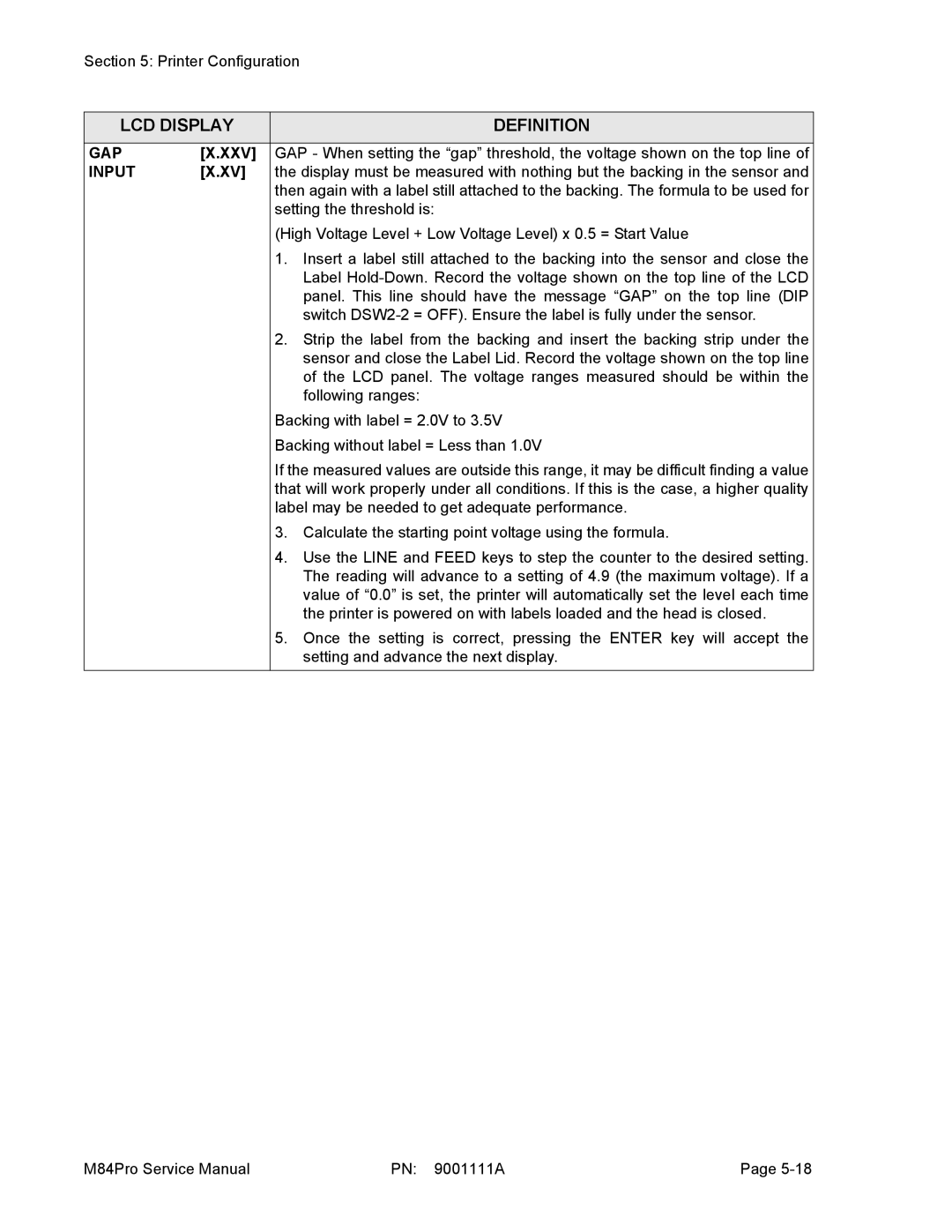
GAP | [X.XXV] | GAP - When setting the “gap” threshold, the voltage shown on the top line of |
INPUT | [X.XV] | the display must be measured with nothing but the backing in the sensor and |
|
| then again with a label still attached to the backing. The formula to be used for |
|
| setting the threshold is: |
|
| (High Voltage Level + Low Voltage Level) x 0.5 = Start Value |
|
| 1. Insert a label still attached to the backing into the sensor and close the |
|
| Label |
|
| panel. This line should have the message “GAP” on the top line (DIP |
|
| switch |
|
| 2. Strip the label from the backing and insert the backing strip under the |
|
| sensor and close the Label Lid. Record the voltage shown on the top line |
|
| of the LCD panel. The voltage ranges measured should be within the |
|
| following ranges: |
|
| Backing with label = 2.0V to 3.5V |
|
| Backing without label = Less than 1.0V |
|
| If the measured values are outside this range, it may be difficult finding a value |
|
| that will work properly under all conditions. If this is the case, a higher quality |
|
| label may be needed to get adequate performance. |
|
| 3. Calculate the starting point voltage using the formula. |
|
| 4. Use the LINE and FEED keys to step the counter to the desired setting. |
|
| The reading will advance to a setting of 4.9 (the maximum voltage). If a |
|
| value of “0.0” is set, the printer will automatically set the level each time |
|
| the printer is powered on with labels loaded and the head is closed. |
|
| 5. Once the setting is correct, pressing the ENTER key will accept the |
|
| setting and advance the next display. |
M84Pro Service Manual | PN: 9001111A | Page |
