M84PRO
Page
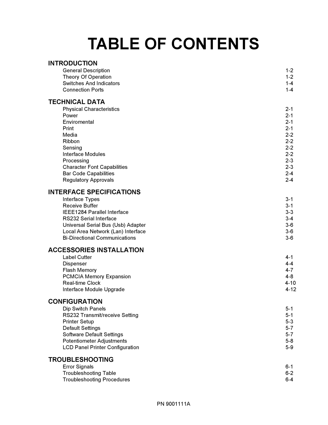
Table of Contents
Diagrams & Schematics
Replacement Procedures
Adjustment Procedures
Factory Resets
Result in Presonal Injury
Introduction
Theory of Operation
General Description
Primary Components
Connection Ports
Switches and Indicators
Switches, Indicators, and Connection Ports
Print
Physical Characteristics
Power
Environmental
Interface Modules
Media
Ribbon
Sensing
Character Font Capabilities
Regulatory Approvals
BAR Code Capabilties
Receive Buffer
Interface Types
Interface Specifications
IEEE1284 Parallel Interface
Specifications
RS232C Serial Interface Signals
Direction Signal Definition
RS232 Serial Interface
Cable Requirements DB9
Host Interconnection
Printer
ENQUIRE/ACK/NAK
Universal Serial BUS USB Adapter
Local Area Network LAN Interface
BI-DIRECTIONAL Communications
Stream Identification
Cancel can
Print Stop DLE
Label Cutter Installation
Accessories Installation
Slide entire print mechanism fully toward the rear
1b, Label Cutter Installation
1c, Label Cutter Installation
Dispenser Installation
2a, Dispenser Installation
2b, Dispenser Installation
2c, Dispenser Installation
Flash Memory Installation
Flash Card Installation
Pcmcia Memory Expansion Installation
4a, Memory Expansion
REAL-TIME Clock Installation
Enter all of the date data required for calender operation
Interface Module Upgrade
DIP Switch Panels
RS232 TRANSMIT/RECEIVE Setting
OFF
DSW1-4
DSW2 OFF
Printer SET UP
DSW2-5
DSW3 OFF
DSW3
Setting
Software Default Settings
Default Settings
Software Default Settings
Default Settings
Default Completed
Potentiometer Adjustments
LCD Panel Printer Configuration
Normal Mode
Configuration Modes
LCD Display Definition
Advanced Mode
SET Calendar
Zero Slash
Auto Online
Print Offset
Card Mode
Copy Start
Xxxxxxx Error
MEM Select CC1
Card Memory
ALL
CARD-MEMORY
Copy Copying
MEMORY-CARDCOPY
Memory Format
Card Format
Input
Service Mode
Service Mode
GAP XXV
Setting the threshold is
Reprint W/FEED
Feed on Error
EYE XXV
Auto Online Feed
EXT PIN 9 Select
Priority Setting
Command LCD
Enable Disable
Counters Mode
Default Settings Mode
Test Print Mode
ALL Clear Mode
MAINTENANCE/FACTORY Mode
Download User Defined Protocol Codes
Clear NON-STANDARD Protocol
QTY000000
HEX Dump Mode
LED LCD Message Beep Error Condition To Clear
Error Signals
Light Print Images
Troubleshooting Table
Image Voids
Ribbon Wrinkling
No Label Movement
Power LED not Illuminated
Smeared Print Images
No Ribbon Movement
Ribbon LED Illuminated
Troubleshooting Procedures
Error LED Illuminated
Label LED is Illuminated
Universal Serial BUS USB Interface
LAN Ethernet Interface
TP Test Module Usage
TP Test Module Usage
Dial Application Description
Ribbon Sensor Operation Verification
Troubleshooting PN 9001111A
Main Circuit Board Replacement
Replacement Procedures
Replacement Procedures
Interface Board Replacement
Interface Board Replacement
Daughter Board Replacement
Daughter Board Replacement
Power Board Replacement
Memory Card Replacement
Power Board Replacement
Panel Board Replacement
Panel Board Replacement
LCD Board Replacement
LCD Board Replacement
Fuse Replacement
Fuse Replacement
Motor Replacement
Motor Replacement
Platen Roller Replacement
10, Platen Roller Replacement
Feed Roller Replacement
11, Feed Roller Replacement
Timing Belt Replacement
12a, Motor and Feed Belt Replacement
12c, Platen Roller Belt Replacement
12d, Ribbon and Rewind Belt Replacement
13, Wiring Harness Connection
Print Head Replacement
14, Print Head Replacement
15, Label-Out Sensor Switch Replacement
LABEL-OUT Sensor Switch Replacement
16, Wiring Harness Connection
17, Label Position Sensor Replacement
Label Position Sensor Replacement
18, Wiring Harness Connection
Ribbon Sensor Replacement
21, Ribbon Sensor Replacement
Cutter Belt Replacement
23a, Cutter Belt Replacement
24, Cutter Circuit Board Replacement
Cutter Circuit Board Replacement
Replacement Procedures
Adjustment Procedures
Print Head Position Alignment
Print Defects Relative Procedure
Print Head Balance Adjustment
Adjustment Procedures
EDI
Ribbon Guide Plate Adjustment
Media
Feed Roller Adjustment
Feed Roller Adjustment
Tightening Timing Belts
Timing Belt Adjustment
Pitch Sensor Assembly
Pitch Sensor Setup for Notch Tags
Label Stock Diagram
Print Position Adjustment
Label GAP Sensor Adjustment
Label Sensor Adjustment
EYE-MARK Sensor Adjustment
LCD Display Adjustment
Offset Label Stop Position Adjustment
Print Darkness Adjustment
Adjustment Procedures PN 9001111A
Factory Settings / Test Print
Factory Resets
Press the Feed key to clear the head counter
Clear Head Counters
Press the Feed key to clear the dispenser counter
Clear Dispenser Counter
Press the Feed key to clear the cutter counter
Clear Cutter Counter
Clear Eeprom
Housing Cover Removal & Installation
Diagrams & Schematics
Ribbon Loading
Media Loading
Pa per Feedin g Direction
Paper Specifications
Paper Feed Direction
Accessories & Sensors Location
Paper Feed Direction
Print Position Reference Diagram
Print Operation Sequence
CONTINUOUS, Pitch Sensor Enabled Head Check Disabled
CONTINUOUS, Pitch Sensor Disabled Head Check Disabled
CONTINUOUS, Pitch Sensor Disabled Head Check Enabled
Msec passes
11, Operation Sequence Chart
12, Operation Sequence Chart
13, Operation Sequence Chart
14, Operation Sequence Chart
15, Operation Sequence Chart
16, Operation Sequence Chart
17, Operation Sequence Chart
18, Operation Sequence Chart
19, Operation Sequence Chart