Section 10: Diagrams & Schematics
CUTTER, OPERATION 1, EXTERNAL PULSE INPUT
| Cut | Head | Pitch sensor (gap) | |
Standby |
| c | d | e |
Print signal input |
|
|
| |
Print 1st page | c | d | e | f |
Cutter operation | c | d | e | f |
Backfeed |
| d | e | f |
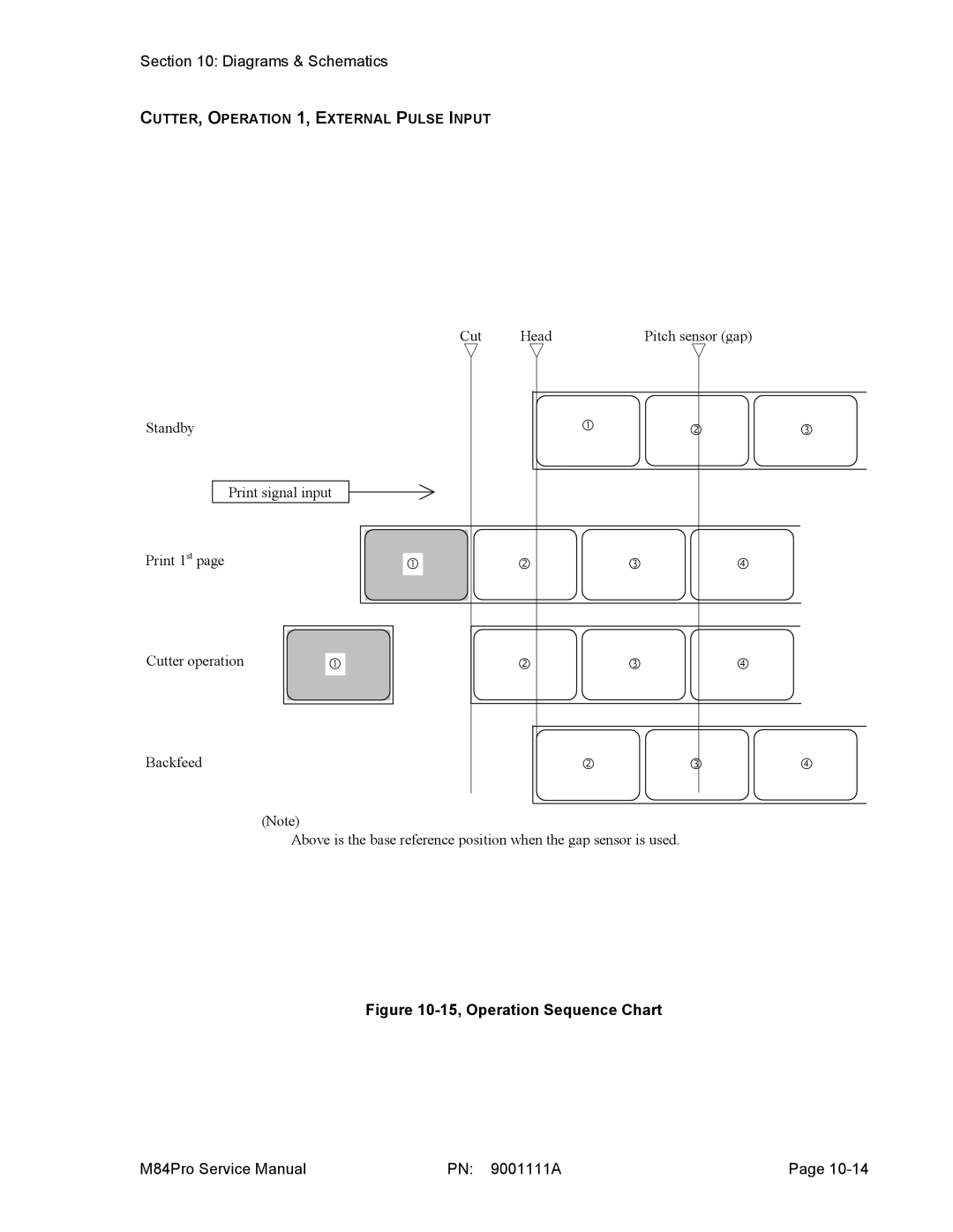
(Note)
Above is the base reference position when the gap sensor is used.
Figure 10-15, Operation Sequence Chart
M84Pro Service Manual | PN: 9001111A | Page |