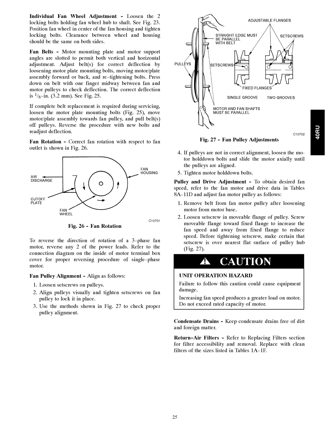
40RU specifications
The Carrier 40RU is a highly regarded solution in the realm of commercial cooling systems, specifically designed for applications requiring reliable, long-lasting climate control. This unit stands out due to its engineering excellence, innovative features, and efficient operation.One of the primary attributes of the Carrier 40RU is its robust construction. Engineered to withstand varying environmental conditions, this unit is built with high-quality materials that promote durability and longevity. The design incorporates corrosion-resistant finishes, which enhances its resilience, especially in outdoor installations.
The Carrier 40RU is equipped with advanced cooling technologies, including variable speed compressors and innovative coil designs. These technologies contribute to its exceptional energy efficiency, allowing the unit to optimize performance while minimizing energy consumption. The variable speed compressors adjust their output based on the current cooling demand, which not only saves energy but also reduces wear and tear on the equipment.
Additionally, the system features a sophisticated control platform that allows for ease of operation and monitoring. This control system offers numerous settings and modes, enabling users to customize their cooling experience based on specific needs. Integration with smart building systems is also possible, providing even greater flexibility and energy management capabilities.
The 40RU model includes a comprehensive filtration system that enhances indoor air quality by effectively capturing dust, allergens, and other particulates. This feature is essential for commercial spaces where maintaining a clean and healthy environment is paramount.
In terms of performance metrics, the Carrier 40RU offers impressive cooling capacities suitable for various applications, from small offices to large commercial buildings. Its noise levels are also minimized through the application of advanced acoustic insulation, ensuring a comfortable environment for occupants.
Moreover, the Carrier 40RU is designed with ease of maintenance in mind. Regular service points are readily accessible, allowing technicians to perform routine checks and repairs efficiently. This design consideration is crucial for minimizing downtime and ensuring the system operates optimally.
In summary, the Carrier 40RU combines rugged construction, energy-efficient technologies, advanced controls, and superior filtration to deliver an outstanding cooling solution for commercial applications. Its versatility, coupled with robust performance characteristics, makes it a preferred choice among HVAC professionals and building managers alike. Whether for new installations or upgrades, the 40RU ensures reliability and comfort in any environment.

